

Figure 26.
Wye "Y" connection.
8.
RECTIFICATION.
a. Potential difference is measured between two points; therefore, a
potential at one point is always measured with respect to another point. The
chassis of a vehicle or an earth ground are normally considered as zero potential
voltages and are the common fixed reference points for almost everything concerning
electricity. An AC (alternating current) is a continually changing current with
time--for a rotor turns in reference to time (RPM). No current can flow unless
there is a potential pressure (voltage) to cause charges of electricity to move.
An AC voltage is one that varies above and below ground potential or zero voltage.
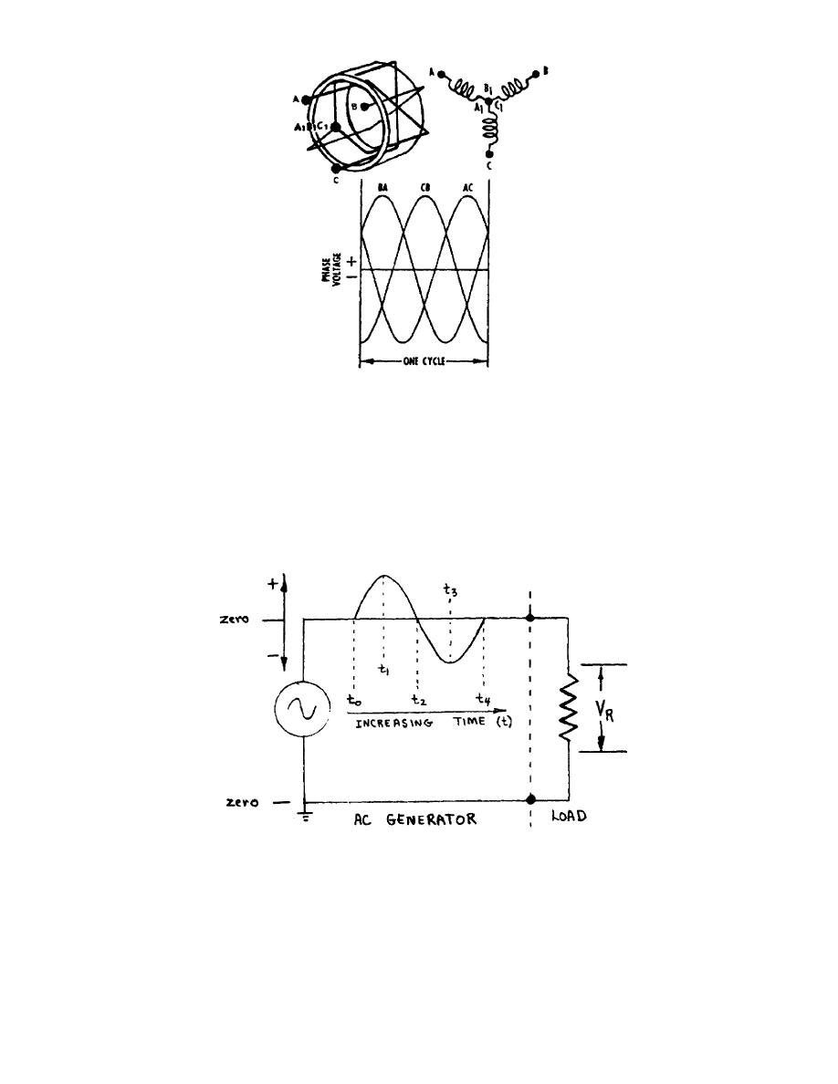
Figure 27.
AC voltage.
b. Figure 27 shows an AC potential being applied to a resistor. This
voltage potential forces an electron current through the resistor. The current
through the resistor allows the voltage to be developed across the resistor.
OS 010, 1-P14

 Previous Page
