• Home
  • Download PDF
  • Order CD-ROM
  • Order in Print

Home > Ordnance Documents and other related manuals > > Figure 29. Half-wave rectifier.
Figure 28. Half-wave rectifier.
Figure 33. Three-phase, full-wave rectifier.

Electrical System Component Repair
Page Navigation
  10    11    12    13    14  15  16    17    18    19    20  

Figure 29.
Half-wave rectifier.
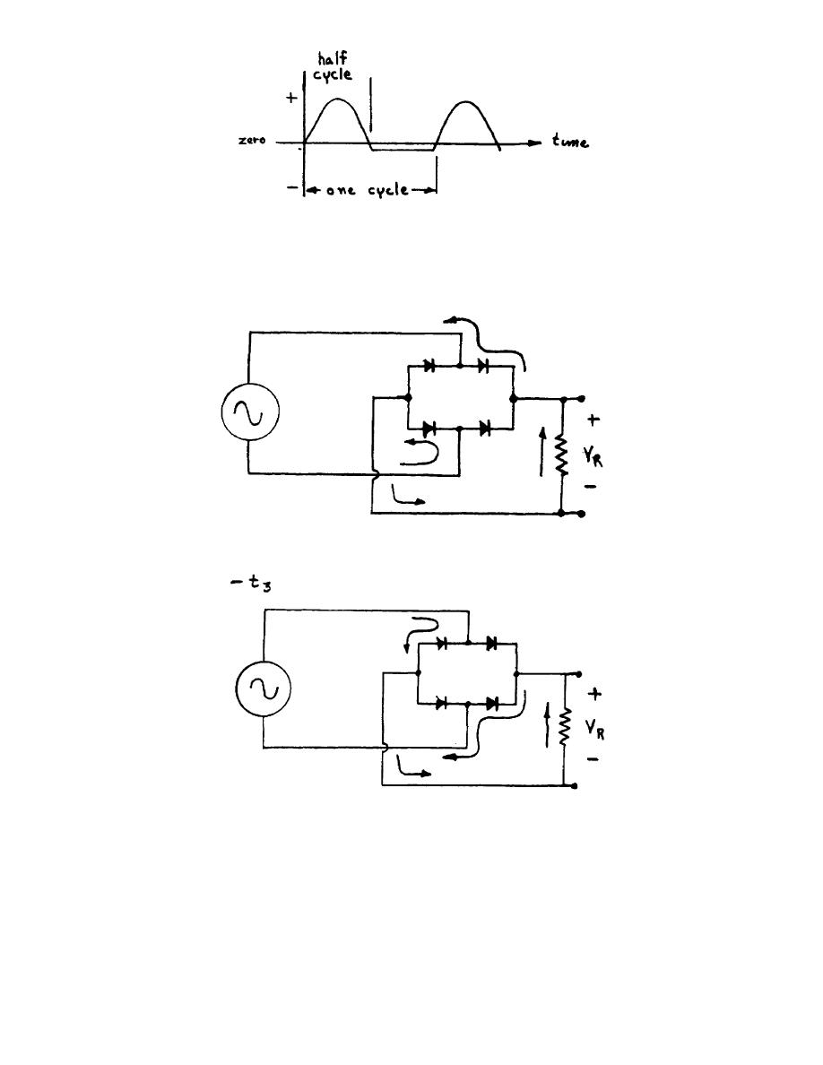
e.  Using four diodes, a circuit can be arranged to cause current to flow in
the same direction through the resistor during both the positive and negative half
cycles.  The circuit is called a full-wave rectifier, for the whole cycle is
developed across the resistor in the positive direction.  (Study figures 30 and 31.)
Figure 30.
Full-wave rectifier t1.
Figure 31.
Full-wave rectifier t3.
OS 010, 1-P16


Western Governors University

< Previous Page
Index ^
Next Page >

Privacy Statement
Press Release
Contact

© Copyright Integrated Publishing, Inc.. All Rights Reserved. Design by Strategico.