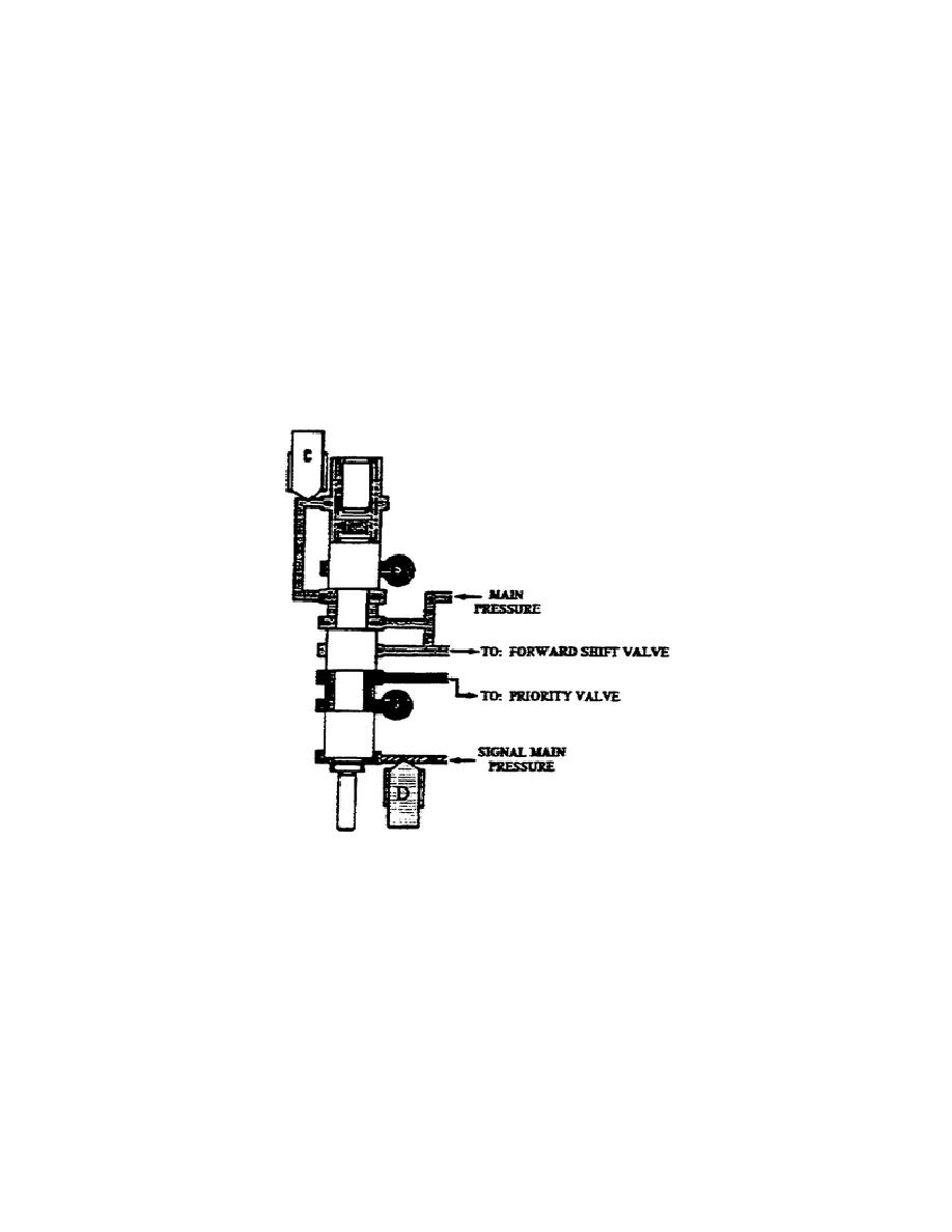
ac. Neutral Shift Valve Assembly (fig. 1-44). This valve assembly
consists of a valve, stop, auto reset plunger, and a calibrated
spring in a bore.
Two solenoids control the movement of this valve.
One controls the
flow of oil to the bottom of the valve; the other controls the flow
of oil to the top of the valve.
Directing signal main pressure to
the reservoir from the bottom of the valve causes spring force to
push the valve down and allows the pressure to flow between the lower
lands to the reservoir. The opposite occurs when the upper solenoid
directs the flow of oil to the reservoir and main pressure (on the
top) moves the valve up against spring force.
NOTE:
Use the auto reset plunger to operate the neutral shift valve
if an electrical failure occurs.
Figure 1-44.
Neutral Shift Valve.
ad. Forward Shift Valve (fig. 1-45). This valve assembly consists
of a valve, stop, and a calibrated spring in a bore.
Two solenoids control the movement of this valve.
One controls the
flow of oil to the bottom of the valve; the other controls the flow
of oil to the top of the valve. When directing reverse pressure to
the reservoir from the bottom of the valve, spring force pushes the
valve down and allows the reverse pressure between the lower lands to
reservoir. This also allows main pressure to flow between the upper
land areas.
45
OD1710


 Previous Page
