

PRINCIPLES GASOLINE/DIESEL FUEL SYSTEMS - OD1620 - LESSON 2/TASK 2
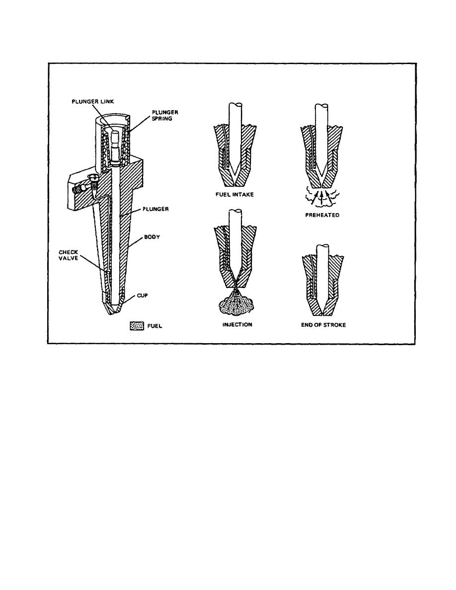
FIGURE 49. DISTRIBUTORTYPE UNIT INJECTORS.
(c) A few degrees before top dead center, at the beginning of the
power stroke, the injector plunger is forced down, causing the fuel charge
to be sprayed out of the cup through the nozzle holes and into the
combustion chamber. The downward movement of the injector plunger is spread
out through the entire power stroke.
(d) There is a small check valve located in the inlet passage of
the injector body. Its purpose is to allow fuel to enter the injector cup
but block high combustion chamber pressure from blowing air into the
injector delivery lines.
e. Unit Injection System (figure 50 on the following page).
(1) Overall System Operation. The unit injection system operates in
the same manner as the multiple unit injection system. The difference is
that rather than using a centrally located unit to
83

 Previous Page
