TM 9-8000
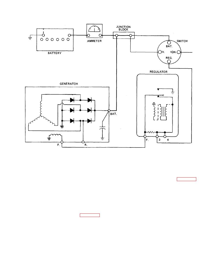
Figure 13-35. Vibrating Point Regulating Circuit
constantly repeating cycle (many times a second) that
the transistor will control and carry the field current. The
serves to limit electrical system voltage. The magnetic
advantage to this configuration is increased contact point
coil force and spring tension are calibrated to maintain
life. This is because the signal current to the transistor is
the desired voltage, which is usually approximately 13.2
low and causes very little arcing.
to 13.8volts in commercial vehicles.
13-29. Solid-State Voltage Regulator (Fig. 13-37). A
(3) During periods of light electrical loads,
solid-state voltage regulator is a static unit that is totally
particularly at high speeds, the system voltage may go
electronic in operation. In this configuration, the contact
too high even with reduced field voltage from the
points are replaced by zener diodes (para 11-7). The
resistor. When this happens, the magnetic coil will pull
zener diodes produce a signal to the base of a transistor
the upper contact into connection with the center contact.
whenever the electrical system voltage reaches the
This will shunt all field current to ground, causing the
desired level. This signal to the base of the transistor
alternator to stop producing current.
reduces or shuts off field current to reduce or stop
alternator output. When the system voltage drops again,
13-28. Transistorized Point Regulator (Fig. 13-36).
the transistor again will allow alternator output. This
The operation of the regulator is essentially the same as
cycle will repeat itself as much as 2000 times per
the vibrating point regulator. The main difference is that
second. Some applications utilize a rheostat to adjust
the contacts only carry a current that is used to trigger a
the resistance of the field current, thereby regulating
transistor. Based on this signal current from the points,
TA233570
13-34


 Previous Page
