

Printed circuit boards mount within
an electrical assembly; the diagrams show them as a series of
long lines broken by short dashes. Inside the enclosure, you
find the designation "A" followed by a number. The letter "A"
indicates a printed circuit board and the number following the
letter indicates number of the circuit board in the electrical
assembly (fig. 1-4).
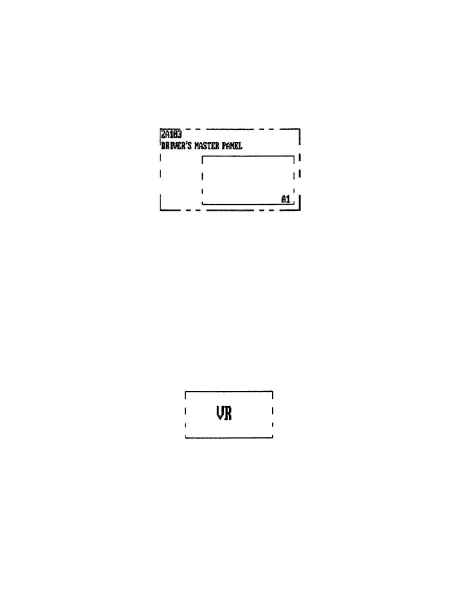
Figure 1-4.
Printed Circuit Board.
Look at the component assembly enclosure lines on sheet 5 of
the hull elementary wiring diagram.
You find they separate
two different components, the driver's master panel and the
instrument panel.
In the lower left corner of the left
enclosure, you find the same identification as in figure 1-4
(above), 2A103, driver's master panel.
Inside the driver's
master panel you find another enclosure designated A1. The A1
enclosure shows a printed circuit the diagram has designed
number 1 in the driver's master control panel.
Voltage Regulators.
The diagrams use the enclosure line to
indicate voltage regulators, representing them with a series
of long lines broken by short dashes. Inside the enclosure,
you find the designation VR (fig. 1-5).
Figure 1-5.
Voltage Regulator Enclosure.
Bus Bars.
Bus bars serve as a common point for several
electrical connections of the same polarity and carries
heavier current than a terminal board. The diagram identifies
bus bars using 2W for positive and 2G for negative.
(See
appendix A for the symbol that represents a bus bar.)
7
OD1706
 Previous Page
