

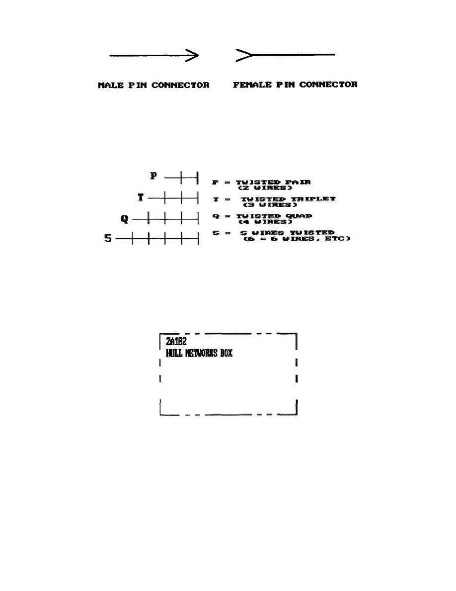
Figure 1-1.
Connector Gender.
Each wiring harness has a different number of wires twisted
together to form the complete harness; depending upon its the
application.
The diagrams show the number of wires twisted
together in a wire harness (fig. 1-2).
Figure 1-2.
Number of Wires Symbol.
Electrical Component Assemblies. On the diagrams, a series of
long lines broken by short dashes encloses all components of
an electrical assembly.
In one corner, the box shows the
alphanumeric assembly code and the name of the component (fig.
1-3).
Figure 1-3.
Electrical Component Assembly.
Look at the component assembly enclosure lines on sheet 4 of
the hull elementary wiring diagram.
You find they separate
two different components, the hull distribution and hull
networks boxes.
In the lower right corner of the bottom
enclosure, you find the same identification as in figure 1-3
(above):
2A102, hull networks box.
If you examine the
connections on the hull networks box closely, you also find it
has both male connectors (J9) and female connectors (J1).
6
OD1706


 Previous Page
