

o
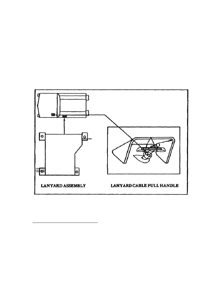
Lanyard Assembly.
The lanyard assembly is used to control and
protect the mechanical cabling which connects the fire extinguishers
to the lanyard cable pull handle.
o
Lanyard Cable Pull Handle.
This component mechanically activates
the engine AFES fire extinguishers no. 2 and crew AFES fire
extinguishers no. 3 and no. 4. The lanyard pull handle is located
on the outside of the vehicle near the driver's hatch. Use of the
lanyard cable pull handle is the only way to activate the second of
two engine compartment fire extinguishers. A 25-pound pull must be
exerted on the lanyard cable pull handle to break the sealed safety
wire on the handle and to discharge the extinguishers. The safety
wire used on the lanyard cable pull handle is installed to prevent
unauthorized or accidental use of the AFES/MDS (see Figure 9).
Figure 9.
AFES Manual Discharge System Components.
PART C - DEACTIVATION/REACTIVATION OF THE AFES
1.
General Safety Instructions.
Before any attempt is made to work on any AFES, it is an absolute must that
the system be deactivated.
Any AFES requiring maintenance or repair is
prone to accidental discharge which in turn may cause personnel injury or
damage to material.
11
OD1700

 Previous Page
