

M2/M3 BRADLEY FIGHTING VEHICLE: TURRET - OD1609 LESSON 3/TASK 1
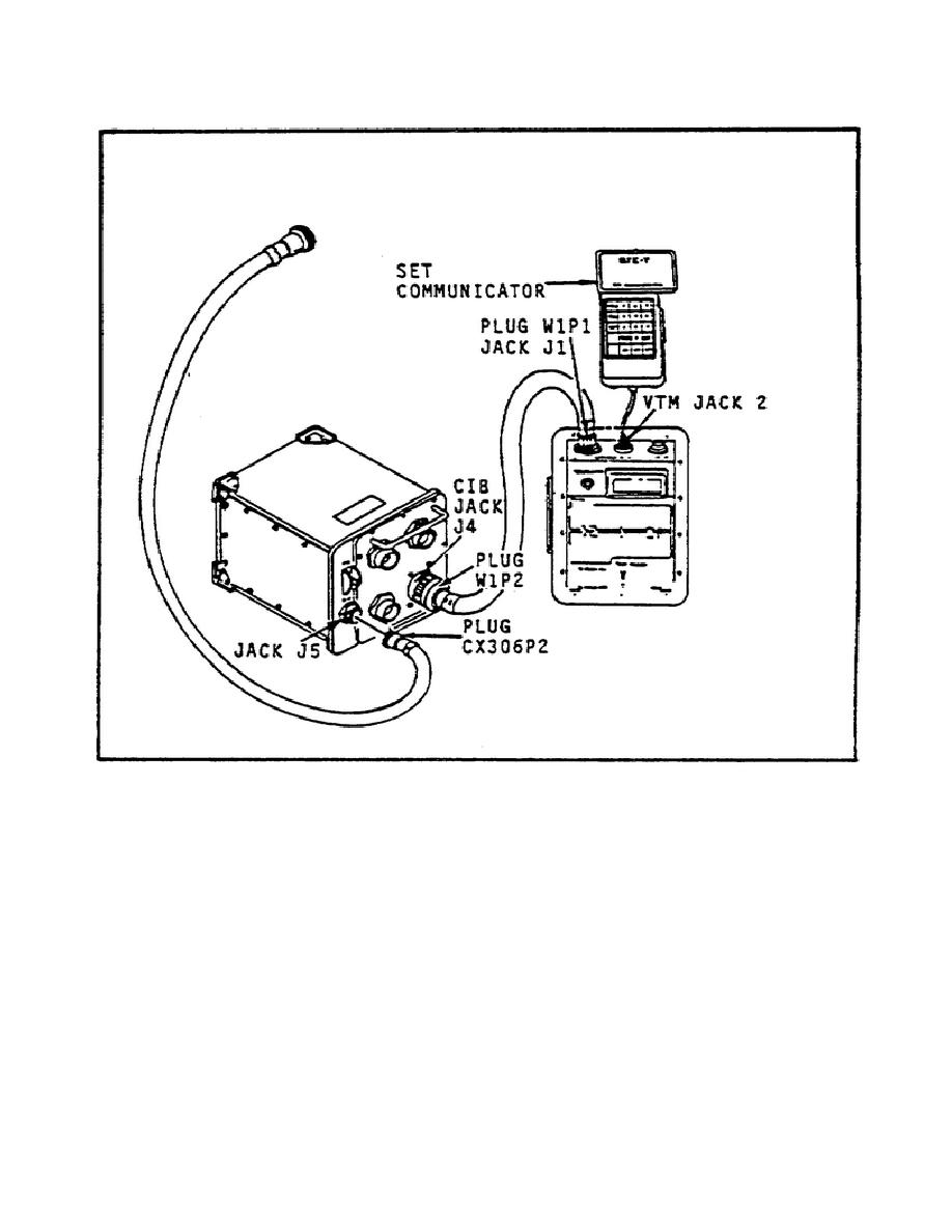
FIGURE 19.
INTERCONNECTING THE STE COMPONENTS.
WARNING
If the turret is operated with the turret shield door open,
soldiers could be killed or injured.
Close and latch the
turret shield door before operating the turret.
(2)
To connect the STE to the diagnostic panel, remove the center turret floor
plate. Move the test equipment to the turret. Then remove the cap from jack J1 on
the diagnostic panel (figure 21 on page 109). Install plug CX306P1 on jack J1 of
the diagnostic panel. Turn the MASTER POWER switch to ON. Then set the CIB ON/OFF
switch to ON and push the VTM circuit breaker ON.
107


 Previous Page
