

The turbine, splined to the turbine shaft, transmits torque to the
transmission input gearing.
At idle speed, the impact of the oil
against the turbine vanes is low; however, at high engine speed, the
impact is much greater, and the turbine produces higher torque.
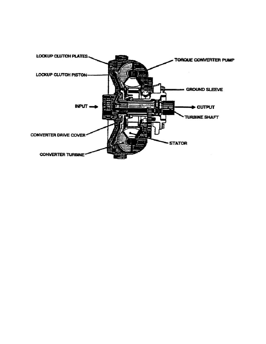
Figure 1-8.
Torque Converter.
Oil thrown into the turbine flows to the stator vanes.
The stator
vanes change the direction of the oil flow (when the stator cannot
rotate), and direct the oil to the pump in a direction that assists
the rotation of the pump. The redirection of oil enables the torque
converter to multiply the input torque.
The greatest torque multiplication occurs when the converter turbine
stalls (stops rotating), and the pump rotates at its highest speed.
As the turbine starts to rotate and gain speed, torque multiplication
decreases.
When the turbine speed approaches pump speed, oil flowing to the
stator begins striking the back of the stator vanes and causes the
stator to rotate in the same direction as the turbine pump. At this
point, torque multiplication stops, and the converter becomes, in
effect, a fluid coupling. See figure 1-9 for a schematic diagram of
the torque converter.
13
OD1710

 Previous Page
