

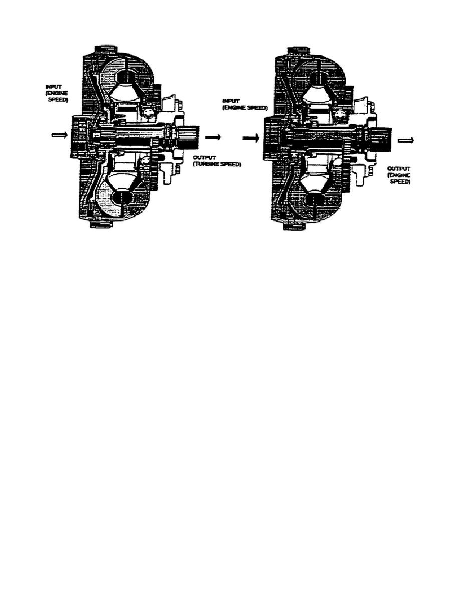
Figure 1-10.
Converter Phase and Lockup Phase.
c. Power Takeoff (PTO)(fig. 1-11).
This transmission has three
engine driven PTOs.
One at each side, near the top, of the input
module, and one at the rear serving as the alternator drive. Since
the engine drives all PTOs, they operate whenever the engine runs.
The engine PTO drive gear bolts to the torque converter pump and
drives an idler gear. The PTO idler gear, splined to one end of the
idler shaft, drives the PTO drive gear attached to the other end of
the idler shaft.
The PTO drive gear meshes with a second PTO gear
and shaft assembly also.
This assembly, consisting of a set of
beveled gears, provides power for the front PTOs (fan drives).
The engine PTO drive gear also drives the rear PTO drive gear in the
input module.
The rear PTO drive gear, splined to one end of the
rear PTO shaft, drives the beveled alternator drive gear attached to
the other end of the rear PTO shaft.
The alternator drive gear
meshes with a beveled alternator driven gear to provide the power for
the alternator.
d. Input Gears (Converter Driven)(fig. 1-12).
The input drive
gear meshes with a driven gear splined to the bevel gear drive shaft.
These straight cut spur gears maintain constant mesh with each other.
The bevel gear carrier consists of the two input bevel gears that
always maintain constant mesh with each other. The drive
15
OD1710


 Previous Page
