

ELECTRONIC PRINCIPLES - OD1647 - LESSON 1/TASK 1
FIGURE 15. INDUCTANCE FACTOR (TURNS).
(b) Coil Diameter. The second factor is the coil diameter.
Figure 1.6 on the following page shows a coil. (B) which has
twice the diameter of coil (A). Physically, it. requires more
wire to construct a coil of large diameter than one of small
diameter with an equal number of turns. Therefore, more lines
of force exist to induce a counter emf in the coil with the
larger diameter. Actually, the inductance of a coil increases
directly as the crosssectional area of the core increases.
Doubling the radius of a coil increases the inductance by a
factor of four.
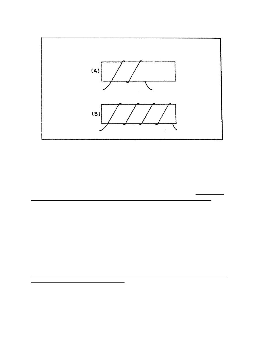
(c) Length of the Coil. The third factor that affects the
inductance of a coil is the length of the coil. Figure 17 on
page 26 shows two examples of coil spacings. Coil (A) has three
turns, rather widely spaced, making a relatively long coil. A
coil of this type has few flux linkages due to the greater
distance between each turn. Therefore, coil (A) has a
relatively low inductance. Coil (B) has closely spaced turns,
making a relatively short coil. This close spacing increases
the flux linkage, increasing the inductance of the coil.
Doubling the length of a coil while keeping the number of turns
the same halves the inductance.
24


 Previous Page
