

ELECTRONIC PRINCIPLES - OD1647 - LESSON 1/TASK 1
changes, the magnetic field changes. This causes relative
motion between the magnetic field and the conductor, and an emf
is induced in the conductor. The emf is called a SELFINDUCED
EMF because it is induced in the conductor carrying the current.
This cmf is also referred to as COUNTER ELECTROMOTIVE FORCE
(cemf). The polarity of the counter electromotive force is in
the opposite direction to the applied voltage of the conductor.
The overall effect will be to oppose a change in current
magnitude. This effect is summarized by Lenz's law which states
that: THE INDUCED EMF IN ANY CIRCUIT IS ALWAYS IN A DIRECTION TO
OPPOSE THE EFFECT THAT PRODUCED IT.
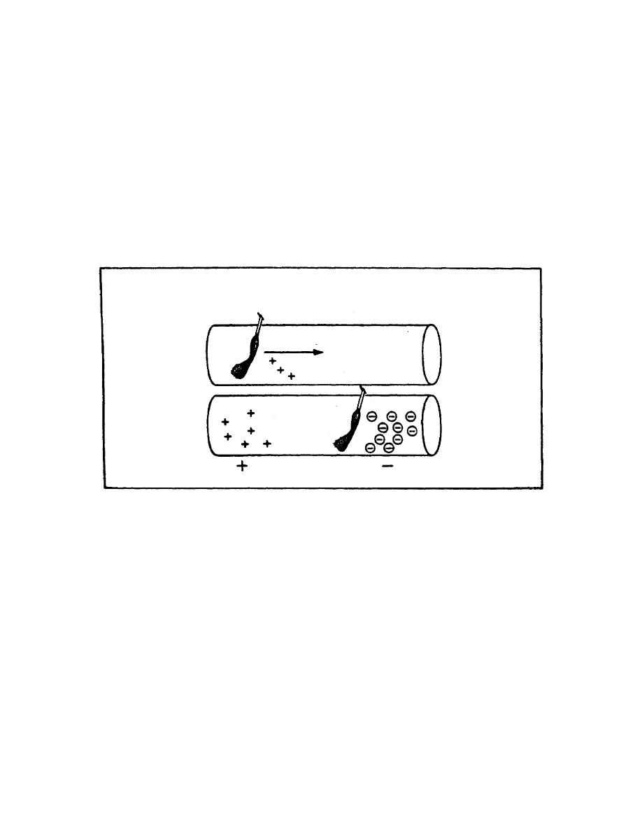
FIGURE 11. MOVEMENT OF A MAGNETIC FIELD THROUGH A CONDUCTOR.
If the shape of the conductor is changed to form a loop, then
the electromagnetic field around each portion of the conductor
cuts across some other portion of the same conductor. This is
shown in its simplest form in figure 12 on the following page.
A length of conductor is looped so that two portions of the
conductor lie next to each other. These portions are labeled
conductor 1 and conductor 2. When the switch is closed, current
(electron flow) in the conductor produces a magnetic field
around ALL portions of the conductor. For simplicity, the
magnetic field (expanding lines of flux) is shown in a single
plane that is perpendicular to both conductors. Although the
expanding field of flux originates at
19


 Previous Page
