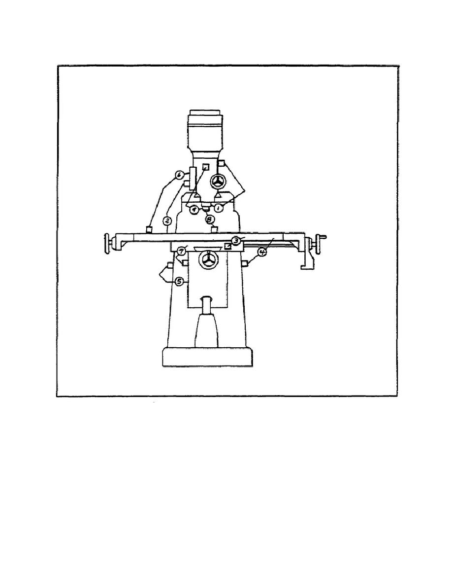
MILLING MACHINE OPERATIONS - - OD1644 LESSON 1/TASK 1
FIGURE 22.
INDICATOR POSITIONS FOR CHECKING ADJUSTMENTS.
(a)
In the rear of the head, between the head and the adapter, is a hex
nut with a 10-24 x 1/2 inch socket head cap screw, used for a lock. Unscrew
this lock screw until you can rotate it freely with your fingers.
(b)
The minimum clutch tension is preset at the factory.
If more
tension is desired, rotate the hex nut to 180 from its present position,
and relock the NO. 10-24 socket head screw.
(c)
It may also be desirable to adjust the travel of the clutch plunger:
49


 Previous Page
