PRECISION MEASURING AND GAGING - OD1642 - LESSON 1/TASK 2
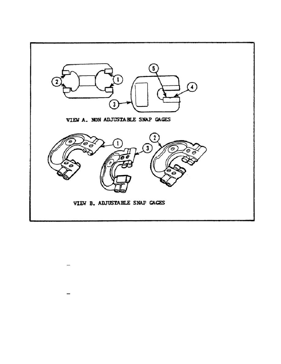
FIGURE 14.
SNAP GAGES.
(d) Using an Adjustable Snap Gage. Before the snap gage is used
to check parts, the GO and NO GO buttons, pins, or anvils must first be set
to the proper dimensions (figure 15, views A through D, on the following
page indicate the steps used for making the proper settings).
1 To make the proper settings, the snap gage should be
clamped in a vise (soft jaws) or a holder (figure 15, view A). Adjust the
GO dimension first or, if desired, reverse the procedure and adjust the NO
GO dimension first.
2 After determining the correct dimension, the gage should be
set. Select a master disk, a precision gage block, or a master plug of the
correct size. Loosen the locking screw (2) (figure 15, view B), and turn
the adjusting screw (3) until the dimension (4) is set.
25


 Previous Page
