PART A - IDENTIFICATION OF
ELECTRICAL AND ELECTRONIC SCHEMATIC SYMBOLS
In order to understand the functioning of an electrical or electronic
circuit, you must be able to "read" the schematic diagram of that
circuit.
A schematic diagram is the road map of the circuit.
In
order to get from one point to another, you must be able to follow
the appropriate route and understand the meanings of the various
symbols found along the way.
1.
Symbols.
Just as the road map uses symbols to represent the
highways, cities, interchanges, and other elements displayed, the
schematic diagram uses symbols to represent the components used to
make up a circuit.
Symbols are used to indicate conductors,
resistors, switches, motors, transistors, and other electrical and
electronic parts.
Components in a circuit schematic are generally
represented by such a symbol and/or a letter designator.
This part
of the lesson reviews many of the symbols used by Army technical
manuals in the schematic diagrams of the appropriate equipment.
2.
Conductors.
Basic to any schematic diagram is the use of
straight lines to indicate conductors.
The conductor is the
"roadway" of the circuit map.
The conductors interconnect the
components of the circuit.
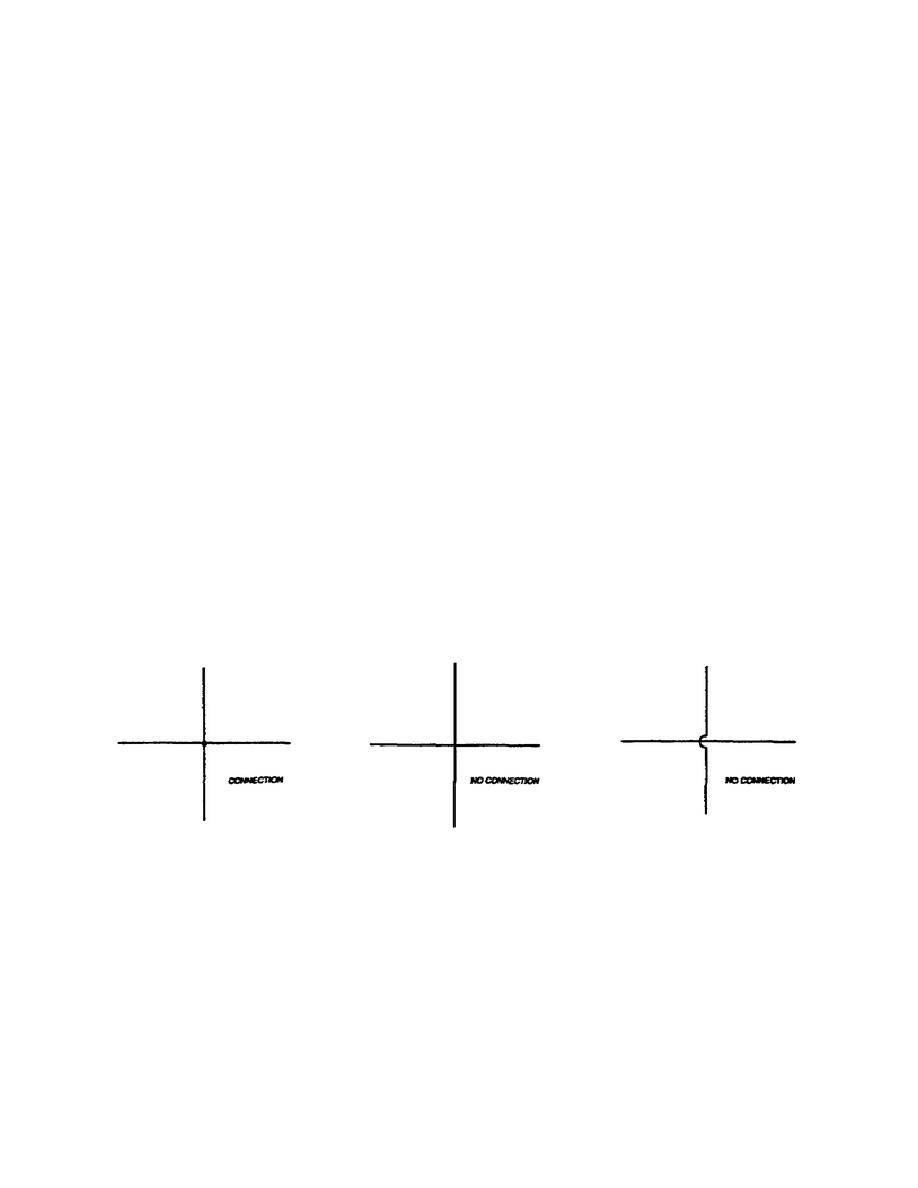
Conductors often cross paths with one
another in the circuit. This may occur with or without their making
electrical contact.
Figure 1-1 illustrates the typical methods for
crossing conductors within a schematic diagram.
Figure 1-1.
Crossing Conductors.
There are many types of conductors used in electrical and electronic
circuits. They may range from the thin layers of metal foil used in
printed-circuit boards to heavy cables used in power transmission.
Cables generally consist of two or more conductors, usually in the
same insulation jacket.
A special type of conductor found in many
electronic applications is the shielded wire or coaxial cable. Here,
the conductor is
2
OD1725


 Previous Page
