WELDING THEORY - OD1650 - LESSON 1/TASK 1
3.
Weld and Welding Symbols
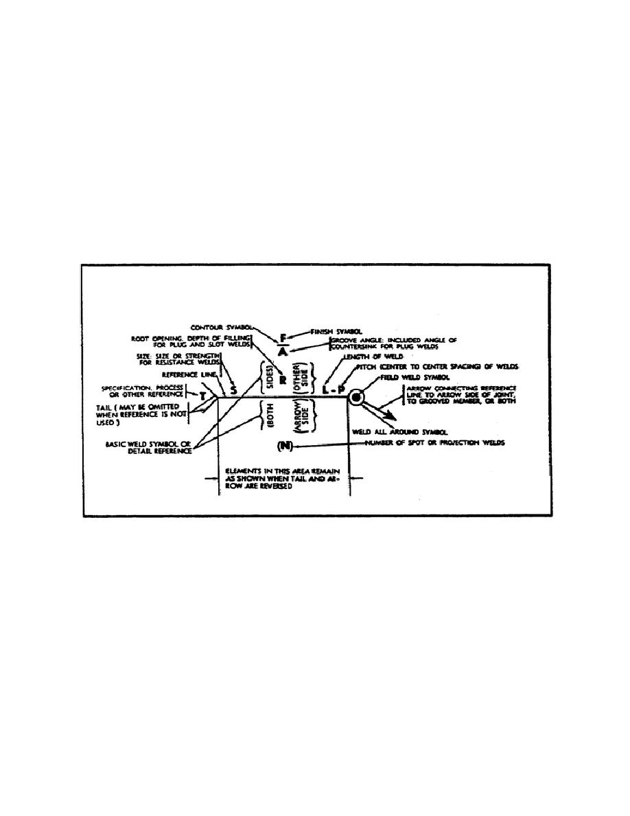
General. Welding symbols provide the means for placing complete and concise welding
a.
information on drawings. The reference line of the welding symbol (figure 2) is used to
designate the type of weld to be made, its location, dimensions, extent, contour, and other
supplementary information. When necessary, a tail is attached to the reference line which
provides specific notations. When such notations are not required the tail is omitted.
FIGURE 2. STANDARD LOCATIONS OF ELEMENTS
OF A WELDING SYMBOL.
Elements of a Welding Symbol. A distinction is made between the term "weld symbol"
b.
and "welding symbol." The "weld symbol" is the ideograph (figure 3, views A and B, on the
following page) that is used to indicate the desired type of weld. The assembled "welding
symbol" consists of the following eight elements, or any of these elements as are necessary:
reference line; arrow; basic weld symbols; dimensions and other data; supplementary symbols;
finish symbols; tail; and the specification, process, or other reference. The location of the
elements of a welding symbol with respect to each other is shown in figure 2.
8


 Previous Page
