PRINCIPLES GASOLINE/DIESEL FUEL SYSTEMS - OD1620 - LESSON 2/TASK 2
(a) Because this system uses fuel from the fuel tank of the
vehicle, its components must be compatible with all approved fuels when the
system is used with a multifuel engine.
(b) The flame fuel pump assembly is a rotary-type, driven by an
enclosed electric motor. The fuel pump receives fuel from the vehicle fuel
tank through the vehicle's supply pump and delivers it to the spray nozzle.
The pump is energized by an ON-OFF switch located on the instrument panel.
(c) The intake manifold flame heater system has a filter to remove
impurities from the fuel before it reaches the nozzle.
(d) Two fuel solenoid valves are used in the flame heater system.
The valves are energized (open) whenever the flame heater system is
activated. The valves ensure that fuel is delivered only when the system is
operating. They stop fuel flow the instant that the engine or the heater
system is shut down.
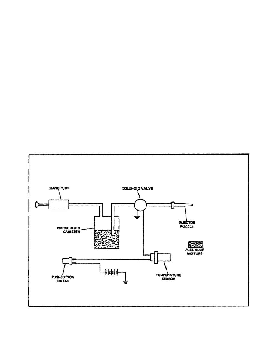
c. Ether Injection System (figure 63).
FIGURE 63.
ETHER INJECTION SYSTEM.
107


 Previous Page
