PRIN. OF INTERNAL COMBUSTION ENGINES - OD1619 LESSON 1/TASK 2
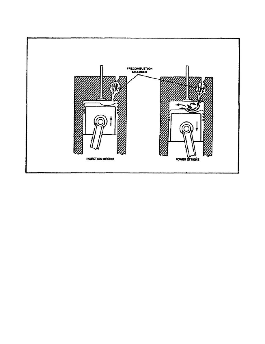
FIGURE 35.
PRECOMBUSTION CHAMBER.
(2) As the injection begins, combustion begins in the precombustion chamber. The
burning of the fuel, combined with the restricted passage to the main combustion
chamber, creates a tremendous amount of pressure in the chamber. The pressure and
the initial combustion cause a superheated fuel charge to enter the main combustion
chamber at a tremendous velocity.
(3) The entering mixture hits the hollowed-out piston top, creating turbulence in
the chamber to ensure complete mixing of the fuel charge with the air. This mixing
ensures even and complete combustion.
This chamber design will provide
satisfactory performance with low fuel injector pressures and coarse spray
patterns, because a large amount of vaporization takes place in the combustion
chamber. This chamber also is not very susceptible to ignition lag, making it more
suitable for high-speed applications.
d. Turbulence Chamber (figure 36 on the following page). The turbulence chamber
is similar in appearance to the precombustion chamber, but its function is
different.
There is very little clearance between the top of the piston and the
head, so that a high percentage of the air between the piston and the cylinder head
is forced into the
40


 Previous Page
