Home
Download PDF
Order CD-ROM
Order in Print
Home
>
Ordnance Documents and other related manuals
>
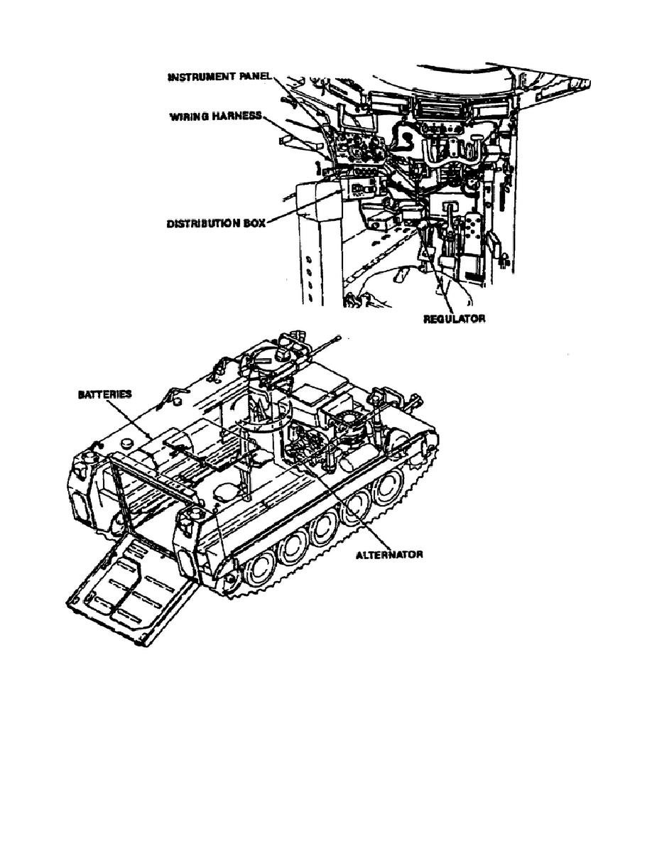
> Figure 1-13. M113A3 Batteries andChaging System.
Part C- Recognition of the New Charging System
Figure 1-14. M113A2 Batteries and Charging System.
Introduction To The M113a3 Armored Personnel Carrier
Page Navigation
11
12
13
14
15
16
17
18
19
20
21
Figure 1-13.
M113A3
Batteries and Charging System
.
gearcase.
The
generator
voltage regulator and the master switch
panel are located in the driver's compartment.
Figure 1-14
illustrates the
M113A2
battery and charging system.
16
OD1712