

ELECTRONIC PRINCIPLES - OD1647 - LESSON 1/TASK 1
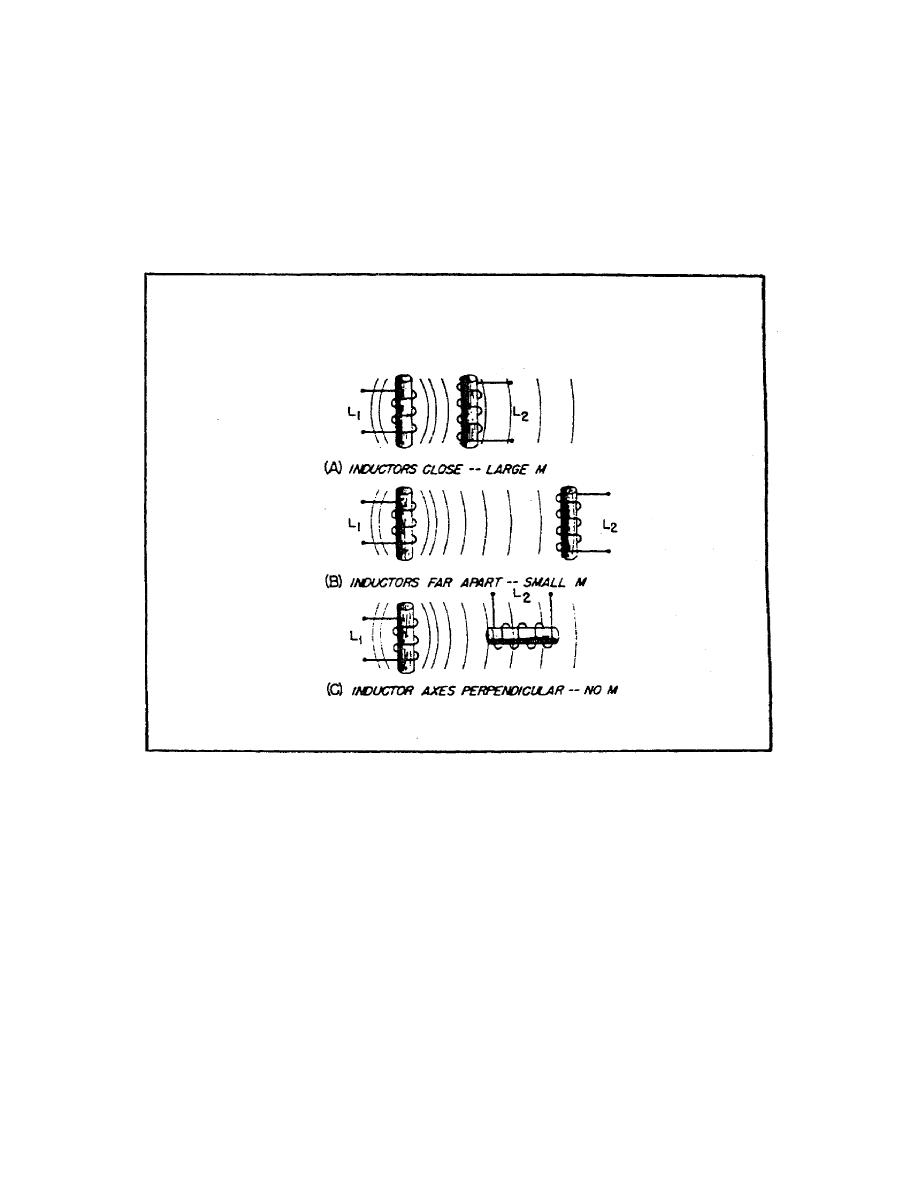
flux common to both coils is small, and the mutual inductance is
low. Conversely, if the coils are close together so that nearly
all the flux of one coil links the turns of the other, the
mutual inductance is high. The mutual inductance can be
increased greatly by mounting the coils on a common iron core.
FIGURE 22. THE EFFECT OF POSITION OF COILS ON MUTUAL
INDUCTANCE.
Two coils are placed close together as shown in figure 23 on the
following page. Coil I is connected to a battery through switch
S, and coil 2 is connected to an ammeter (A). When switch S is
closed, as in figure 23, view A, the current that flows in coil
I sets up a magnetic field that links with coil 2, causing
induced voltage in coil 2 and a momentary deflection of the
ammeter. When the current in coil 1 reaches a steady value, the
ammeter returns to zero. If switch S is now opened as in figure
23, view B, the ammeter (A) deflects momentarily in the opposite
direction, indicating a momentary flow of current in the
opposite direction
36

 Previous Page
