ELECTRONIC PRINCIPLES - OD1647 - LESSON 1/TASK 1
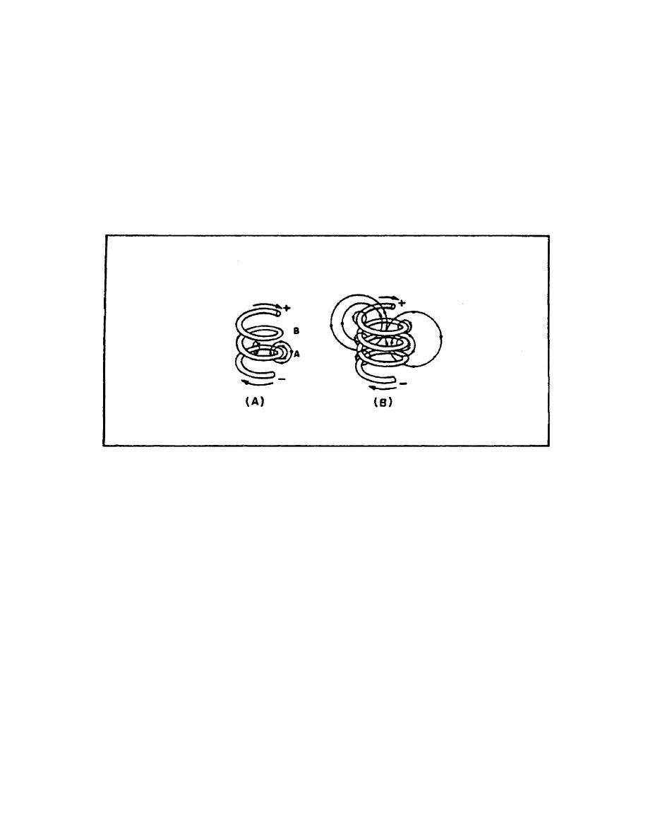
Figure 13 shows a conductor formed into a colt.
Current through one loop produces a magnetic field that
encircles the loop in the direction as shown in figure 13, view
A. As current increases, the magnetic field expands and cuts
all the loops as shown in figure 13, view B. The current in
each loop affects all other loops. The field cutting the other
loop has the effect of increasing the opposition to a current
change.
FIGURE 13. INDUCTANCE.
(2) Classification of Inductors. Inductors are classified
according to the core type. The core is the center of the
inductor just as the core of an apple is the center of an apple.
The inductor is made by forming a coil of wire around a core.
The core material is normally one of two basic types:
softiron or air. An ironcore inductor and its schematic
symbol (which is represented with lines across the top of it to
indicate the presence of an iron core) are shown in figure 14,
view A, on the following page. The aircore inductor may be
nothing more than a coil of wire, but it is usually a coil
formed around a hollow form of some nonmagnetic material such as
cardboard. This material serves no purpose other than to hold
the shape of the coil. An aircore inductor and its schematic
symbol are shown in figure 14, view B.
(3) Factors Affecting Coil Inductance. There are several
physical factors which affect the inductance of a coil. They
include the number of
22


 Previous Page
