

Lesson 2/Learning Event 2
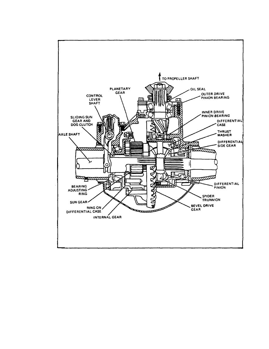
FIGURE 18. DIFFERENTIAL.
The drawing shows what the differential looks like. Notice the holes in the two halves of
the case where the four stems of the spider can seat. When the two halves of the case
are bolted together with the spider or cross-shaft in place and the ring gear is bolted in
place to the left half of the case, the entire unit must rotate when the ring gear turns.
Also notice that there is a bearing surface in the two sides of the case to support the
machined shoulders of the bevel side gears.
30

 Previous Page
