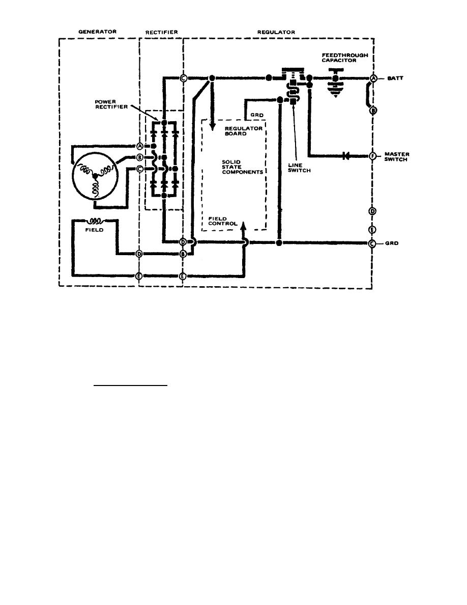
Figure 9.
Simplified diagram.
(1) The cover and case should be inspected for cracks, stripped threads,
or other damage and replacement made as needed. When cover is reinstalled, a new
O-ring should be used to insure proper sealing. Lightly coat the O-ring with
silicone grease prior to installation.
(2) If the preceding components check okay, it is fairly certain that
only the regulator circuit board could be defective if the unit is non-operational.
d. Additional tests. To further test the regulator it must be connected to
the test stand in an operational system. Procedures for this were covered in
lesson 4, so you should know what precautions are required.
(1) In lesson 4, two functions of the regulator were tested.
The first
was a test of the line switch (load relay).
(2) The second was a regulation check, where the system was operated at
2,000 RPM and a 100-ampere load applied.
(a) During the regulation test the regulator was adjusted for an
output of 28 volts DC.
(b) During the complete procedure after adjustment, the voltage
should maintain stable between 27.5 and 28.5 volts no matter where the RPM or load
is varied.
OS 010, 5-P10


 Previous Page
