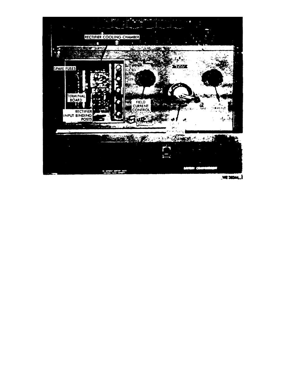
Figure 8.
Rectifier cooling chamber and front control panel.
e. Proper resistance for the regulator test circuit is set with the
regulator load resistor selector. Four positions of the selector (fig 7) choose
resistance values of 1/4, 1-1/2, 2-1/4, and 7 ohms. The fifth position is OFF.
f. There are three pairs of remote meter testing binding posts. Connection
to the 0-32VDC variable power supply is provided at the DC power supply remote
meter testing posts. Connection to the millivolt meter is provided at the
millivolt meter remote meter testing binding posts. The DC voltmeter remote meter
testing binding posts provide for external testing and comparison using the DC
g. Illumination for the control panel is provided by a work light.
The
two-position work light switch provides ON-OFF control of this light.
h. The varidrive unit is controlled by the start-stop buttons. The buttons
control a magnetic switch supplying power to the varidrive unit. The "drive on"
indicator lamp illuminates when the varidrive unit is operating.
i. There are three two-position field switches. The external field switch
controls the external voltage to the unit being tested. Proper grounding of the
generator (under test) field circuit is determined by the setting of the field
common switch. The field circuit switch closes the field circuit of the unit under
test. The "Manual" position is used when no regulator is connected in the circuit.
With a regulator in the circuit, the switch is set to the "Regulator" position.
OS 010, 3-P10


 Previous Page
