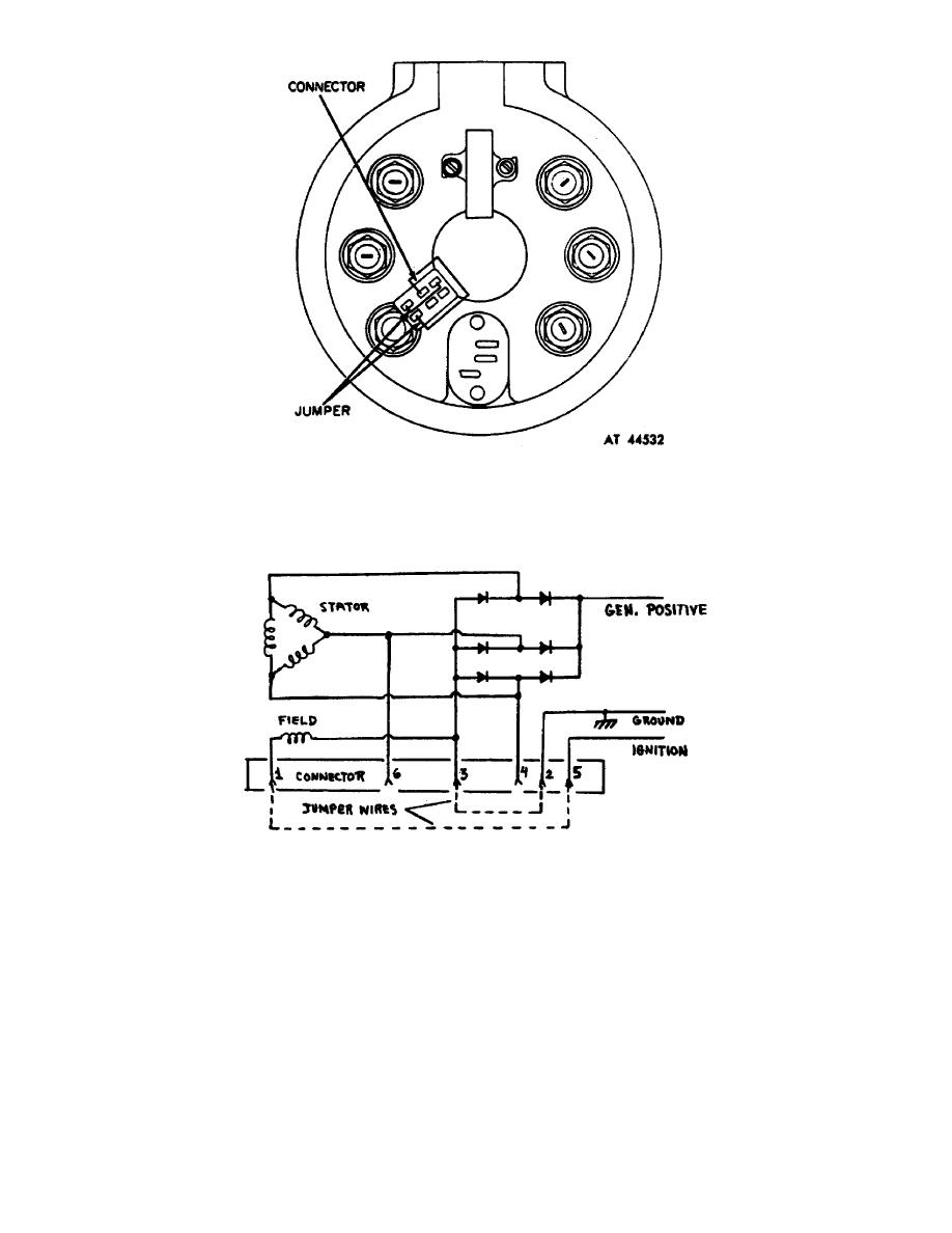
Figure 8.
Installation of jumper wires.
(1) Once the jumper wires are in place, the rectifier assembly is
grounded and the ignition terminal is directly connected to the field circuit.
Figure 9 shows what is happening schematically.
Figure 9.
Schematic operation.
(2) After installing the drive end housing on the generator it may be
connected to the test stand (B, foldout 6).
(a) Connect cables from generator positive (A, foldout 6) to test
stand G+ and from generator ground (frame) to G-.
OS 010, 4-P12


 Previous Page
