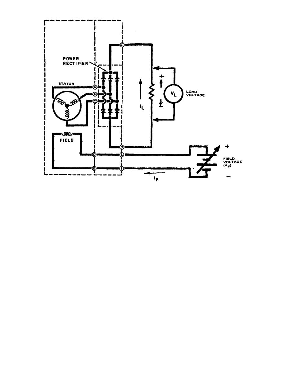
Figure 3.
The generator.
b. Another scheme may be used to control the amount of magnetic flux in the
field; this is shown in figure 4. Here the field winding is connected across the
battery that is being charged. Notice that it is connected through a regulator
switch.
(1) When the voltmeter indicates above normal, we open the switch and
shut off the field current (IF). This causes the magnetic flux to decrease,
thereby decreasing the output of voltage.
(2) When the voltmeter indicates below normal, we close the switch and
apply the field current (IF). The current IF produces an increasing magnetic flux
increasing the output voltage.
(3) By our observations, we can regulate the output voltage by opening
and closing the regulator switch. However, an automatic system has been devised to
open and close the switch, thus producing the regulator that we use today.
c. The first type of automatic regulator incorporated a relay with a set of
normally closed contacts (fig 5). This is a simplified circuit but it can be used
to explain the operation.
(1) The relay is voltage sensitive. Its sensitivity can be controlled,
over a small range, by a rheostat or a variable resistor.
OS 010, 5-P3


 Previous Page
