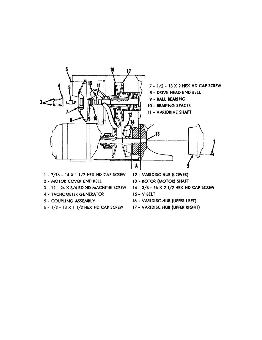
b. The varidrive assembly (fig 13) is shock-mounted to prevent control
panel vibration. A speed transmission and motor are embodied in this self-
contained unit. The front panel drive speed control allows the unit's RPM to be
varied over a wide range. Rotating the control counterclockwise causes the
moveable lower varidisc hub, mounted on the rotor (motor) shaft, to slide toward
its companion varidisc. The added tension on the V-belt causes the moveable
varidisc on the driven shaft to retract against the spring. This simultaneous
action causes the V-belt to assume a larger diameter on the lower varidisc and a
smaller diameter on the upper varidisc. The speed of the driven shaft is therefore
increased while motor speed remains constant.
Figure 13.
Varidrive and tachometer generator assembly.
c. We have previously discussed the tachometer indicator meter mounted on
the meter panel. That indicator is electrically connected to the tachometer
generator mounted on the end of the varidrive shaft. When the varidrive speed is
increased the direct current output of the generator increases, causing an up-scale
deflection on the tachometer. When the tachometer circuit is properly adjusted the
speed of either driving head can be read directly from the meter.
d. The electrical wiring diagram (fig 14) is included at this point so that
you can familiarize yourself with the location of all the components we have
discussed in this lesson. Locate the items discussed but do not study the diagram
extensively at this time. Selected circuits will be discussed in following lessons.
OS 010, 3-P16


 Previous Page
