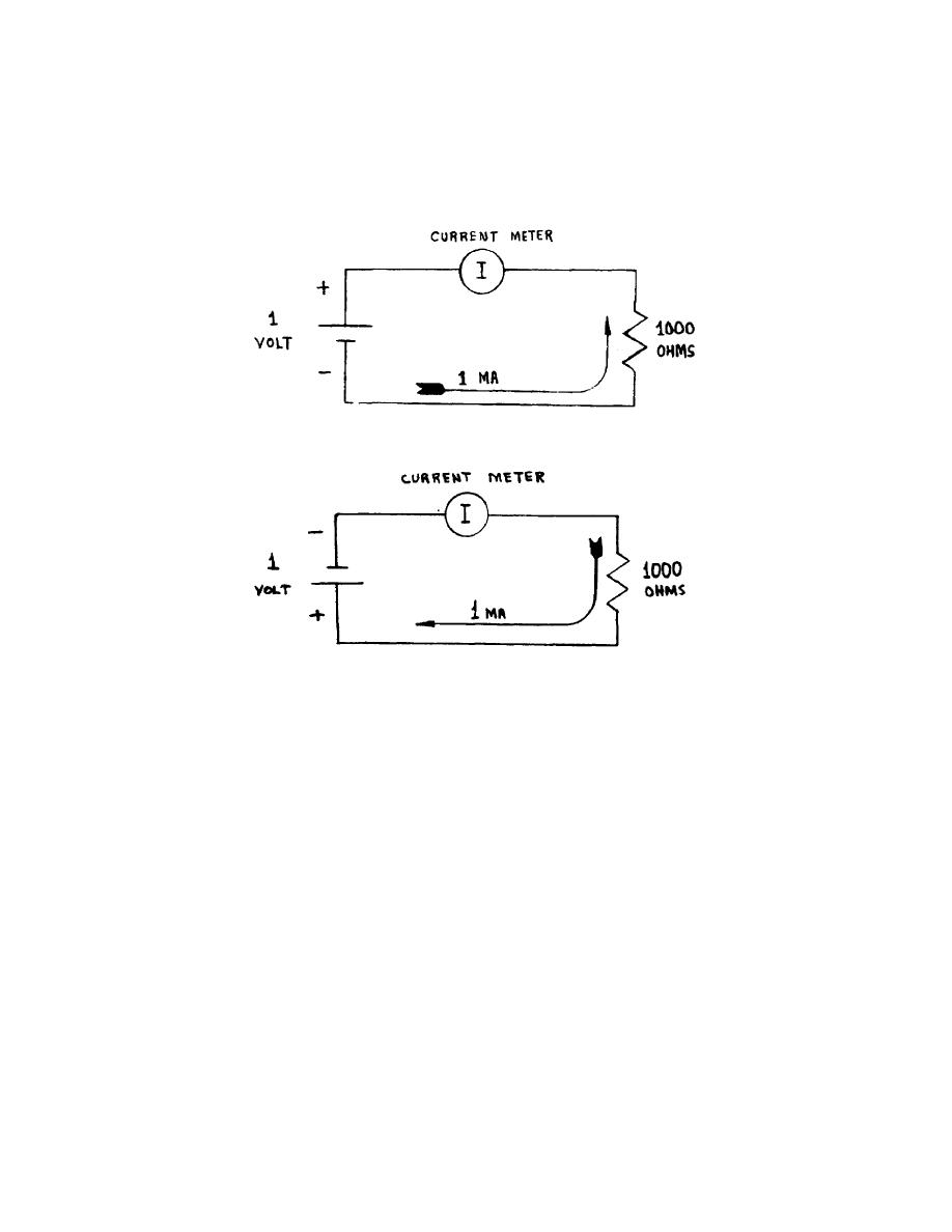
g. Figure 5 illustrates a simple circuit in which one milliampere (1mA) of
electron current will flow. The zero center scale current meter deflects to the
right and indicates a 1mA reading. If the battery potential is reversed (fig 6),
1mA of electron current will flow through the resistor in the opposite direction.
The zero center scale current meter will be deflected to the left and indicate 1mA
of current. You should note that for this discussion one current has been called
forward current (fig 5) and the other reverse current (fig 6). Recording the
voltage current relationship which exists illustrates the linearity of resistive
circuits (fig 7).
Figure 5.
Forward current.
Figure 6.
Reverse current.
3.
DIODES.
a. The conventional diode is an electrical device whose resistance varies
nonlinearly with the voltage applied to it (fig 8). When the diode is forward
biased it passes maximum current. When it is reverse biased it passes minimum
current. The extremes between maximum and minimum currents are so great that for
all practical purposes it is said the diode will only pass current in the forward
biased direction. Figure 9 is the performance curve of a typical diode showing
forward and reverse current characteristics. The plot of the 1,000-ohm resistor is
included for comparison.
b. The curve in the lower left portion shows that some reverse current will
flow when the diode is reverse biased. The amount is very small and the current
increases very little until the breakdown voltage is reached. For the conventional
diode rectifier this breakdown voltage occurs at several hundreds of volts.
Overheating will occur when the breakdown voltage is reached in a conventional
diode. The heat generated causes the diode to
OS 010, 1-P4


 Previous Page
