

MILLING MACHINE OPERATIONS - OD1644 - LESSON 1/TASK 1
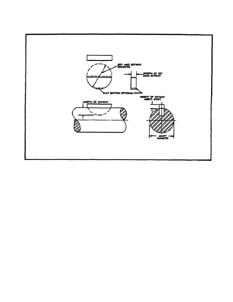
FIGURE 20.
WOODRUFF KEY AND KEYWAY DIMENSIONS.
inch in diameter and 2/32 or 1/16 inch wide; a number 1012 woodruff key
would be 12/8 or 1 1/2 inches in diameter and 10/32 or 5/16 inch wide.
(3)
Milling Woodruff Keyslots.
The woodruff keyslot milling cutter is
mounted in a spring collet or adapter which has been inserted in the spindle
of the milling machine or milling attachment (figure 21 on the following
page).
With the milling cutter located over the position in which the
keyway is to be cut, the workpiece should be raised, or the cutter lowered,
until the peripheral teeth come in contact with the workpiece.
At this
point the graduated dial on the vertical feed adjustment should be locked
and the clamp on the table set. Using the vertical feed, with the graduated
dial as a guide, the workpiece is raised or the cutter lowered, until the
teeth come in contact with the workpiece. At this point, the graduated dial
on the vertical feed adjustment should be locked and the clamp on the table
set. Using the vertical feed, and with the graduated dial as a guide, the
workpiece is raised, or the cutter lowered, until the full depth of the
keyslot is cut, completing the operation.
44


 Previous Page
