

A wide variety of light indicators are also used to provide important
information to the operator.
These may include such items as
indicator lamps with various color lenses such as a power on
indicator, a flashing neon bulb such as a high temperature alarm, a
digital display such as a range readout, or a graphic display such as
a screen on an oscilloscope. The light indicator may be provided by
such sources as lamps, fluorescent or neon tubes, or light-emitting
solid-state devices.
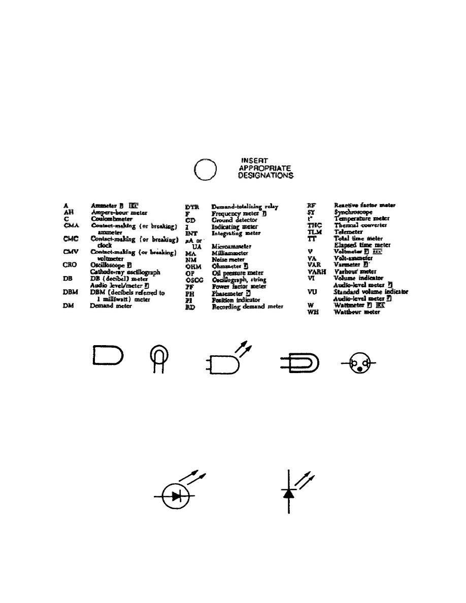
Generally, light indicators or displays are
shown on schematics by one of the symbols illustrated in figure 1-22
and are labeled with the letters "DS."
Figure 1-21.
Readout Devices.
Figure 1-22.
Light Indicators.
An exception is often made when the light source is a light-emitting
diode (LED) or a liquid-crystal display (LCD).
These solid-state
devices may be represented symbolically as above, or they may be
represented by the symbols shown in figure 1-23 and labeled with the
letters "CR."
Figure 1-23.
Solid-State Light Indicators.
14
OD1725


 Previous Page
