

The Fire Support Team (FIST) connector, located on the LD/R, allows for
remote operation of the G/VLLD. When used, the FIST controls override the
functions of the local controls.
5.
As a fire control systems repairer, you must understand the functional
operation of the G/VLLD set to perform the maintenance necessary to keep
your equipment operating at peak performance.
You must identify the
components and assemblies within the major components, and understand how
they function together in the operation of the system.
Before proceeding
with the functional description of the G/VLLD, it is beneficial to identify
some of the subassemblies included in the discussion.
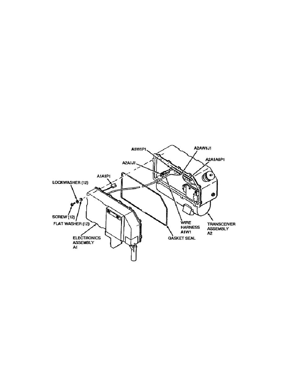
The functional operation of the G/VLLD takes place primarily through the
interaction of the two major subassemblies within the LD/R: the electronics
assembly and the transceiver assembly.
Wire harness A1W1 electrically
connects the two subassemblies. Figure 1-10 shows an exploded view of the
LD/R with the two subassemblies separated.
Figure 1-10.
LD/R Subassemblies.
As shown in figure 1-10, the subassemblies have alphanumeric reference
designators.
The figure shows the electronics assembly designated A1 and
the transceiver assembly designated A2. Use these reference designators to
help you identify and
13
OD1722


 Previous Page
