

LATHE OPERATIONS - OD1645 - LESSON 1/TASK 1
spindle.
Thus two speeds are available with each position of the belt on
the cone; if the cone pulley has four steps, eight spindle speeds are
available.
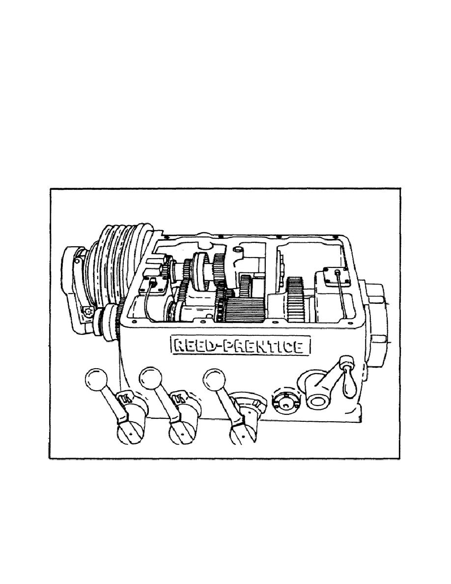
(b) The geared headstock shown in figure 5 is more complicated but more
convenient to operate, because the speed is changed by changing or by
shifting the gears. This headstock is similar to an automobile transmission
except that it has more gear-shift combinations and, therefore, has a
greater number of speed changes.
A speed index plate, attached to the
headstock, indicates the lever positions for the different spindle speeds.
To avoid damage to the gear teeth, the lathe is always stopped before the
gears are shifted.
FIGURE 5.
SLIDING GEAR TYPE HEADSTOCK.
(c) Figure 5 shows the interior of a typical geared headstock that has
16 different spindle speeds. The driving pulley at the left is driven at a
constant speed by a motor located under the headstock. Various combinations
of gears in the
10


 Previous Page
