

M2/M3 BFV: FIRE CONTROL SYSTEM - OD1608 - LESSON 2/TASK 1
FIGURE 50.
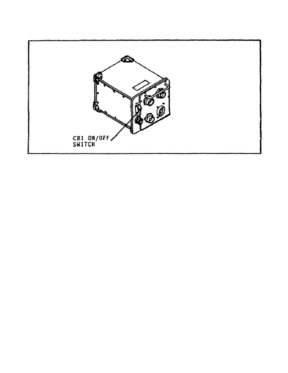
THE CIB ON/OFF SWITCH.
(3) Set the CIB ON/OFF switch (figure 50) to OFF.
(4) Install
the
SETCOM
on
VTM
jack
J2
(figure
51
on
the
following page).
(5) Hook up the VTM to the CIB by installing plug W1P1 onto VTM
jack J1 and plug W1P2 onto CIB jack J4 (figure 51).
(6) Next, install plug CX306P2 onto CIB jack J5 (figure 51).
(7) Now that the STE interconnections have been made, the STE
can be connected to the vehicle distribution box or the diagnostic
panel.
(a) To connect the STE to the vehicle distribution box
(figure 52 on page 69), first remove the cap from jack 1A1J14 (DCA 3)
on the vehicle distribution box.
Install plug CX1203P1 onto jack
1A1J14 (DCA 3).
Then hook up the STE to the vehicle by installing
plug CX306P1 onto CX1203 connector P2.
WARNING
If the turret is operated with the turret shield
door open, soldiers could be killed or injured.
Close and latch the turret shield door before
operating the turret.
67


 Previous Page
