

M2/M3 BFV: FIRE CONTROL SYSTEM - OD1608 - LESSON 1/TASK 3
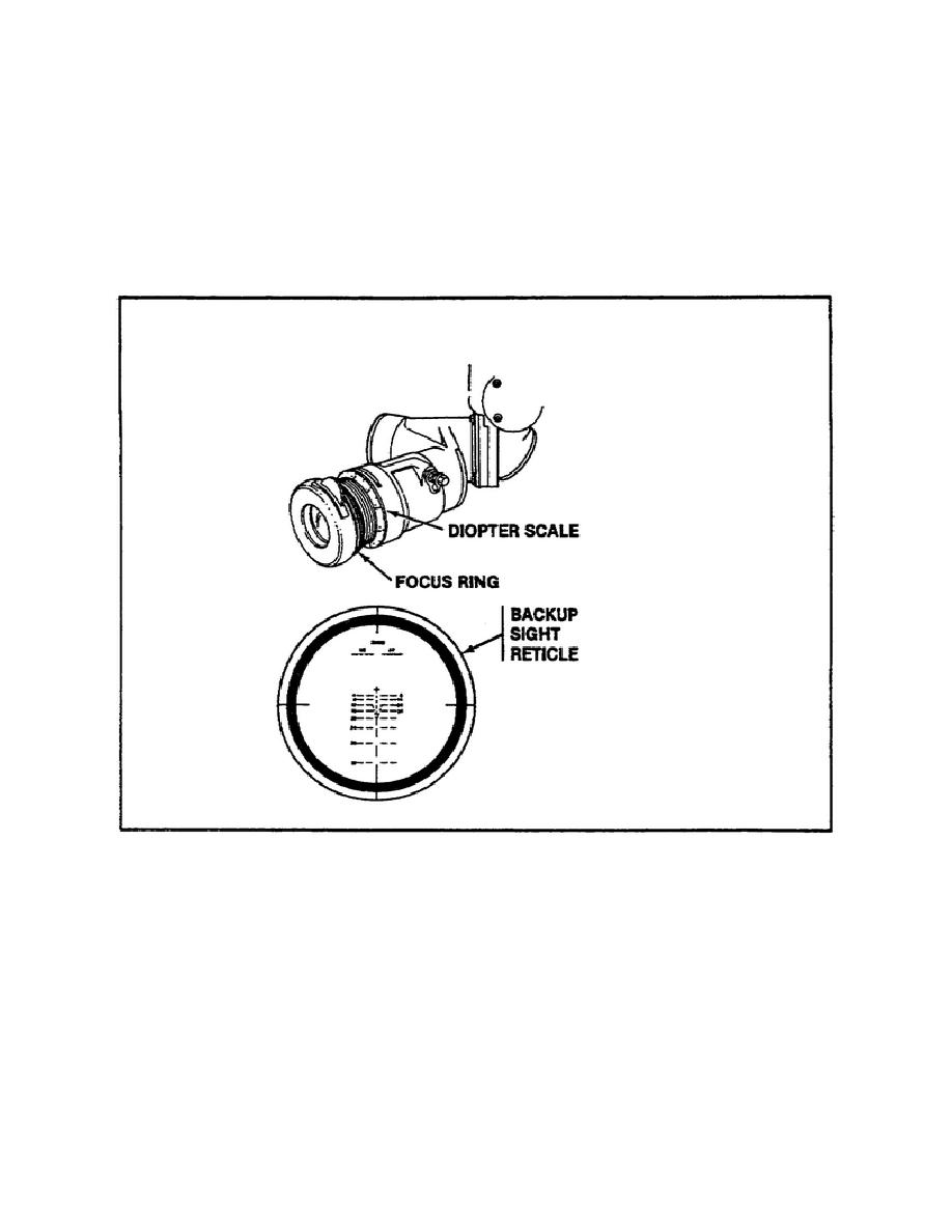
turn the focus ring (figure 21) left and right until the reticle is
in focus. Since each operator has a different diopter setting, it is
convenient for the mechanic to make note of his setting for future
use.
The diopter setting is determined for each individual by
focusing the reticle and then reading the number on the diopter scale
(behind the eyepiece) opposite the white mark on the focus ring.
FIGURE 21.
FOCUSING THE BACKUP SIGHT.
(3) Next, look at the aiming point image in the backup sight
reticle. If the aiming point image is in the center of the reticle
crosshairs, the backup sight is correctly boresighted, and no further
adjustments are required. If, however, the aiming point image is not
in the center of the backup sight reticle crosshairs, boresighting
procedures must continue.
(4) When the aiming point image is not in the center of the
backup sight reticle crosshairs, an elevation linkage adjustment must
be performed. To perform this adjustment, follow these steps:
27


 Previous Page
