

M2/M3 BFV:
STEERING SYSTEM - OD1605 - LESSON 1/TASK 1
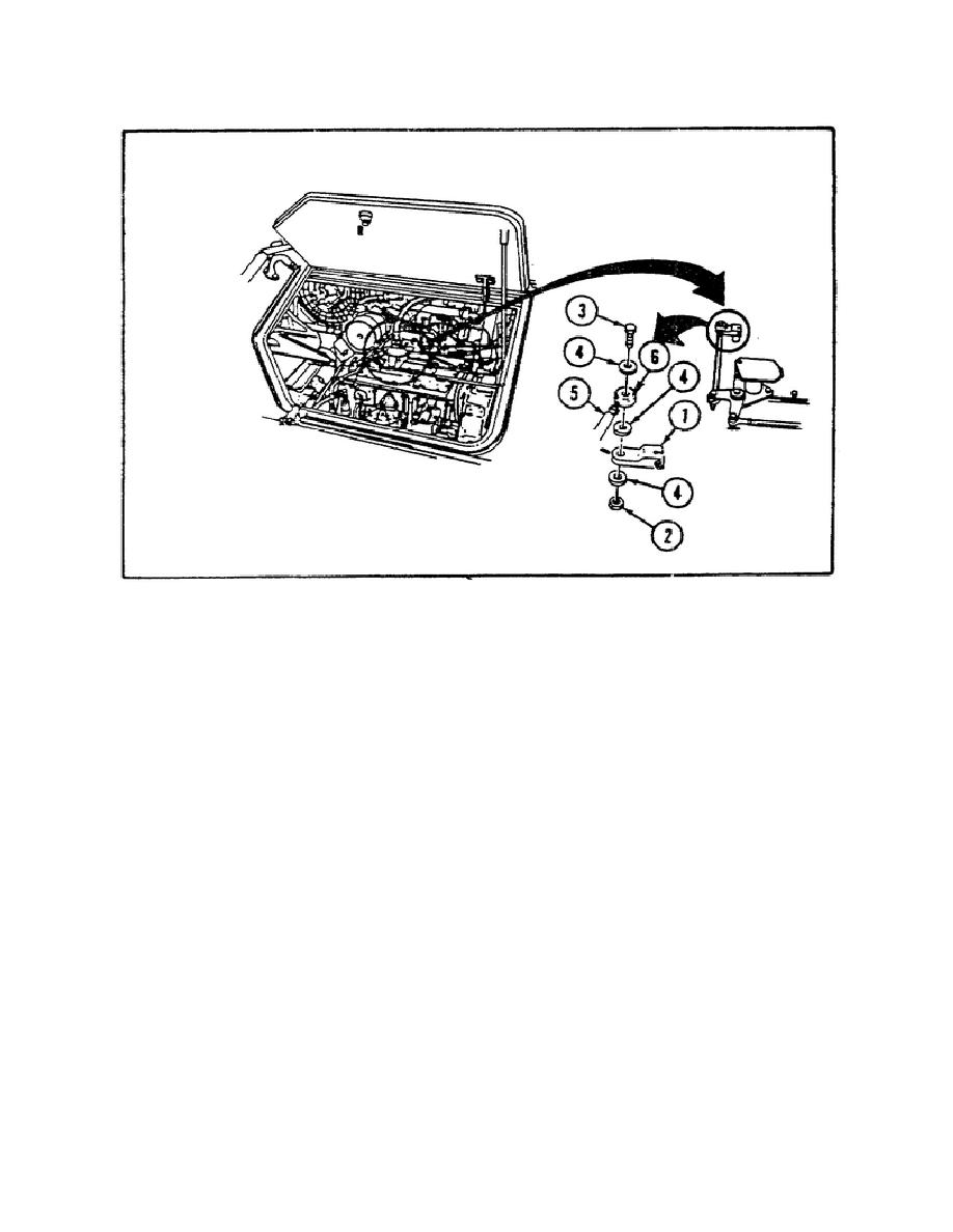
FIGURE 8.
DISASSEMBLING LEVER.
Step 5.
He then discards the locknut as required and rotates the
lever forward and back to determine if the lever is frozen or
binding.
Step 6.
The lever does not bind or appear frozen during the above
check, so he checks link bearing (6) to see if it is frozen (see
figure 8). Unlike the lever, SGT Fields finds that the link bearing
is frozen. He then must replace the connecting link as described in
paragraph 5b on page 19.
Step 7.
After replacing the connecting link, he test operates the
vehicle to make sure that the problem has been corrected.
It is
during this test operation that he finds the steering system is still
inoperational and must be troubleshot again.
Step 8. SGT Fields begins troubleshooting the system and must repeat
steps 1 through 5 as described above. When he gets to step 6, unlike
the previous troubleshooting, the link bearing is not frozen and
rotates easily when moving the connecting link back and forth.
Step 9.
The removed components are reassembled onto the lever so
that the connecting link can be disconnected at the bellcrank in
order to check for
16


 Previous Page
