

Lesson 2/Learning Event 2
driving balls and hold them in the proper position during vehicle turns. A pilot, spring,
and pin are mounted in the center of the outside axle at the CV joint to control the
movement of the cage and balls.
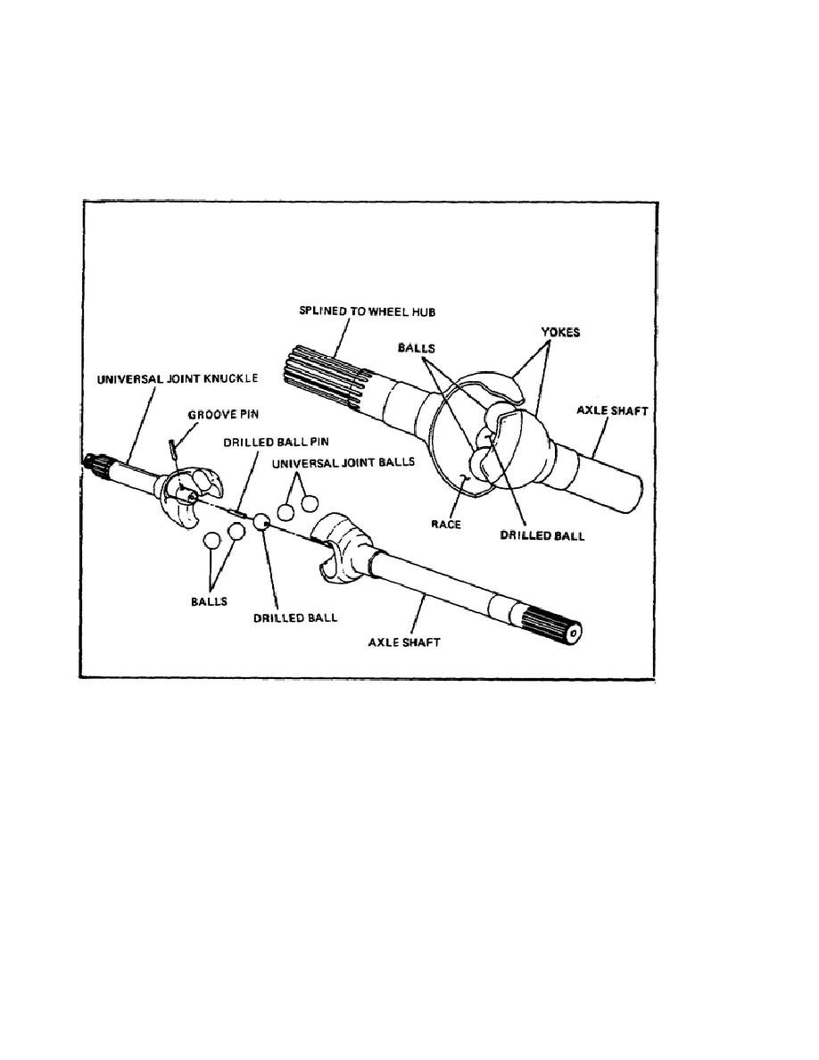
FIGURE 22. BENDIX-WEISS CONSTANT VELOCITY JOINT.
The Bendix-Weiss joint also uses steel balls to transmit power at an angle but has slightly
different construction. Notice in the illustration that both the inner and outer axle shafts
have yokes made as part of the shaft. The yokes contain races for smooth steel balls.
These races are long grooves that permit the balls to move back and forth as the drive
angle of the shaft changes. There are four balls mounted between the two yokes in the
races. A fifth ball is mounted in the center to lock the four outer balls in place. The
center ball is held in place with a pin. When the joint is assembled, the steel balls form a
tight fit between the inner and outer shafts. The tight fit is necessary since there is no
cage to hold the balls, and movement is controlled by friction between the connecting
parts.
39


 Previous Page
