

3-36. Bracket Mount removal/replacement.
Removal. Remove the four sets of mounting hardware (77, 78,
79, and 80) and the mount (76).
Replacement.
Secure
the
bracket
mount
with
four
sets
of
mounting hardware.
3-37. Ground Terminal E1 removal/replacement.
Removal.
Remove the mounting hardware (82, 83, and 84) and
the terminal E1 (81).
Replacement.
Secure
the
terminal
E1
with
the
mounting
hardware.
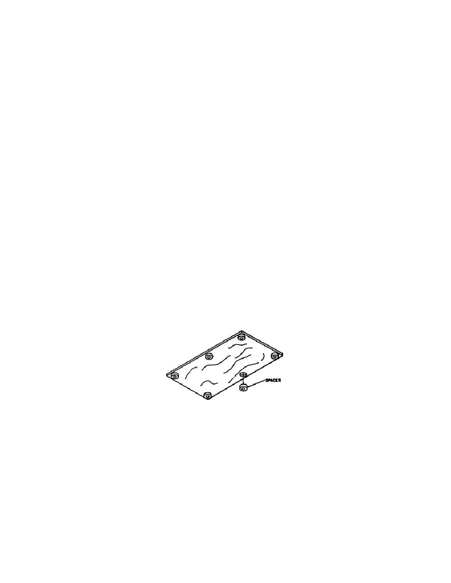
3-38. Printed Circuit Board Mounting Bushing removal/replacement.
Removal.
Refer to figure 1-28.
--
Remove the A2 assembly (step 3-22) or the A3 assembly
(step 3-23).
--
Use a very sharp knife to cut away the old bonding
material holding the mounting bushing to the printed
circuit board. Pull the bushing out of its hole.
--
Carefully scrape away the residue of the old bonding
material.
Figure 1-28.
Circuit Board Mounting Bushings.
Replacement.
--
Use naphtha and soft tissue to clean the bushing contact
surface of the printed circuit board.
NOTE:
The two part sealant used for bonding after mixing does not
fully harden.
It will stay partially soft.
There is no
solvent for part one (base). Xylene is the solvent for part
two (accelerator).
54
OD1716


 Previous Page
