

Figure 1-15.
Special Tools and Test Equipment.
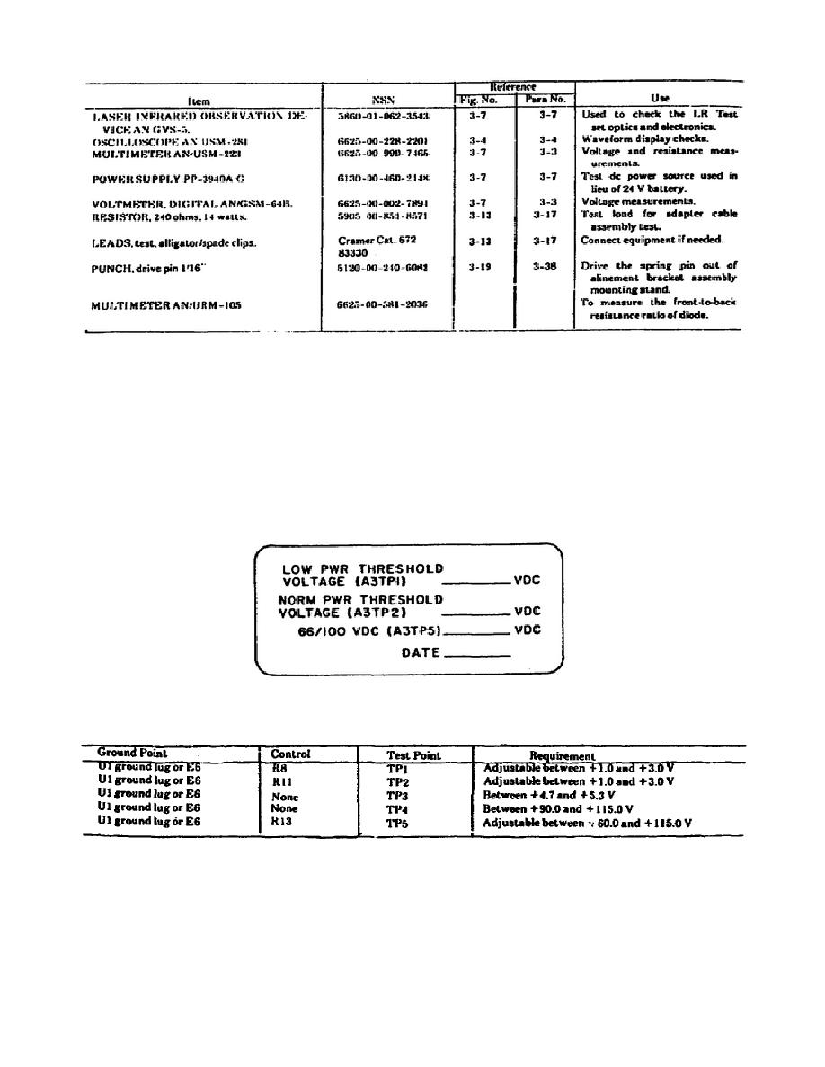
To conduct the voltage measurements on the power supply board
assembly A3 (figure 1-11, item 24), refer to the power supply board
assembly A3 voltage label (figure 1-16).
The indicated voltage
levels must match those shown on the label.
Figure 1-17 shows the
required voltage measurements for the power supply board assembly.
Figure 1-18 illustrates the location of the test points on the
circuit board.
To conduct the voltage measurements, perform the
following steps.
Figure 1-16.
Power Supply Board Voltage Label.
Figure 1-17.
Power Supply Board Voltage Measurements.
23
OD1716


 Previous Page
