

Perform the procedures indicated under PREPARATION FOR USE
(page 4/5).
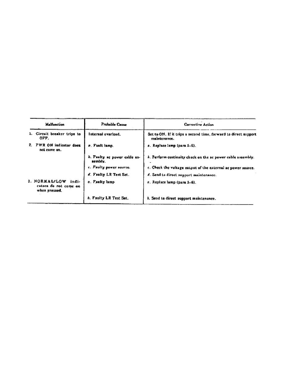
Set ON/TRIPPED OFF circuit breaker to ON.
If the circuit
breaker trips to TRIPPED OFF, go to troubleshooting procedures
(figure 1-4), malfunction 1.
Observe PWR ON indicator. If the indicator does not light, go
to troubleshooting procedures (figure 1-4), malfunction 2.
Press LASER OUTPUT NORMAL and LASER OUTPUT LOW indicators.
Observe whether indicators light when pressed.
If indicator
does not light, go to troubleshooting procedures (figure 1-4),
malfunction 3.
Figure 1-4.
Troubleshooting the LR Test Set.
If adapter cable assembly is used, connect it to 0-40 volts
direct current (VDC) power supply and adjust power supply
voltage to +24 VDC.
Place multimeter test leads between the center terminal of the
battery adapter and its cap.
If the output voltage is not
23.0 to 23.5 VDC, send the adapter cable assembly to direct
support maintenance.
Refer to TM 11-5860-201-30 for instructions on:
--
Mounting the LR to the alignment bracket assembly.
--
Troubleshooting the LR.
--
Using the adapter cable assembly with the LR.
8
OD1716


 Previous Page
