

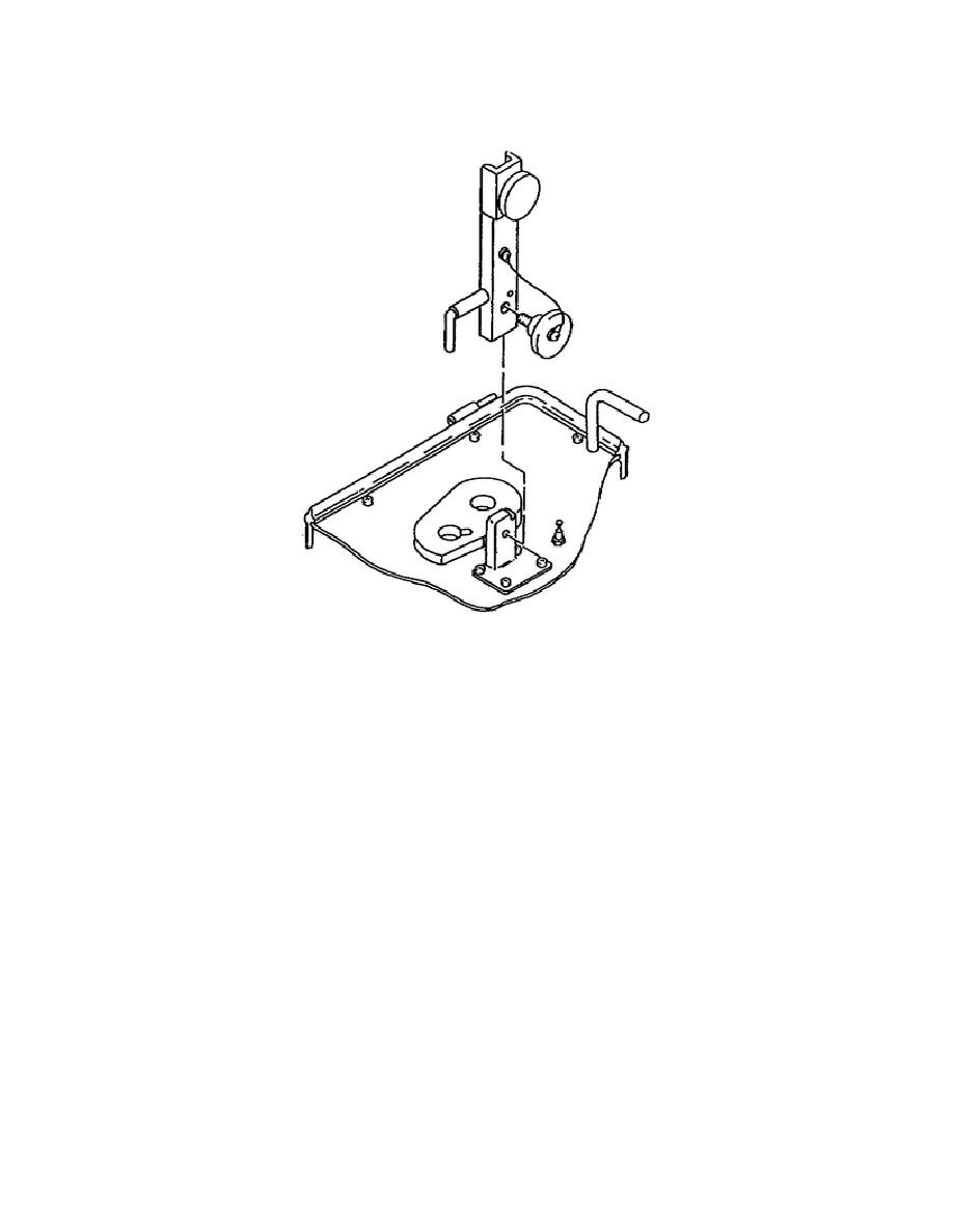
the alignment bracket assembly from the cover and install it on the
front panel of the LR Tester (see figure 1-2).
Figure 1-2.
Alignment Bracket Assembly Installation.
NOTE:
Set the ON/TRIPPED OFF circuit breaker to TRIPPED OFF before
connecting the AC power cable assembly to the power source.
Remove the AC power cable assembly from the cover and connect it to
the PWR 115 V, 50-420 hertz (Hz) connector on the front panel.
Connect the AC power cable assembly to the 115 volts alternating
current (VAC) source.
4.
Controls and Indicators.
The front panel of the LR Test Set contains the controls and
indicators used in the unit's operation. It additionally houses the
connectors for power and signal monitoring (see figure 1-3).
5
OD1716


 Previous Page
