

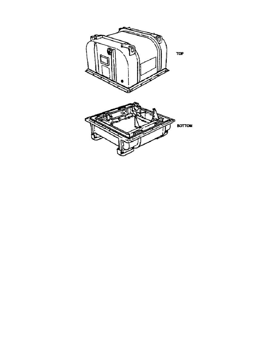
Figure 1-5.
View of Transmission Shipping/Storage Container.
This concludes part D.
Part E provides the name, location, and
description of the major assemblies of the X200-4 transmission.
PART E - LOCATION AND DESCRIPTION OF TRANSMISSION
MAJOR ASSEMBLIES
During this part of the subcourse you will learn the name,
description,
and
location
of
the
major
assemblies
of
the
transmission. Figure 1-6 is provided to assist you in locating their
position on the transmission.
The following information, in conjunction with figures 1-7 through
figure 1-12, will provide you with more detailed data.
1.
Transmission Top Components.
This
assembly
is
located
on
the
top
portion
of
the
transmission/center housing assembly. It consists of the top cover,
the control valve assemblies, the push start control rod and the
vacuum modulator.
The separator plate and the oil transfer plate
assembly are also parts of the transmission top components. You must
remove all transmission top components
15
OD1714


 Previous Page
