• Home
  • Download PDF
  • Order CD-ROM
  • Order in Print

Home > Ordnance Documents and other related manuals > > Figure 12. APU Electrical Diagram.
Figure 11. APU Fuel Return Line Location And Components.
Figure 14. APU Wall Mount Main Harness Connector B.

Troubleshooting the Auxiliary Power Unit (APU) M992 carrier, Ammunition,
Page Navigation
  10    11    12    13    14  15  16    17    18    19    20  

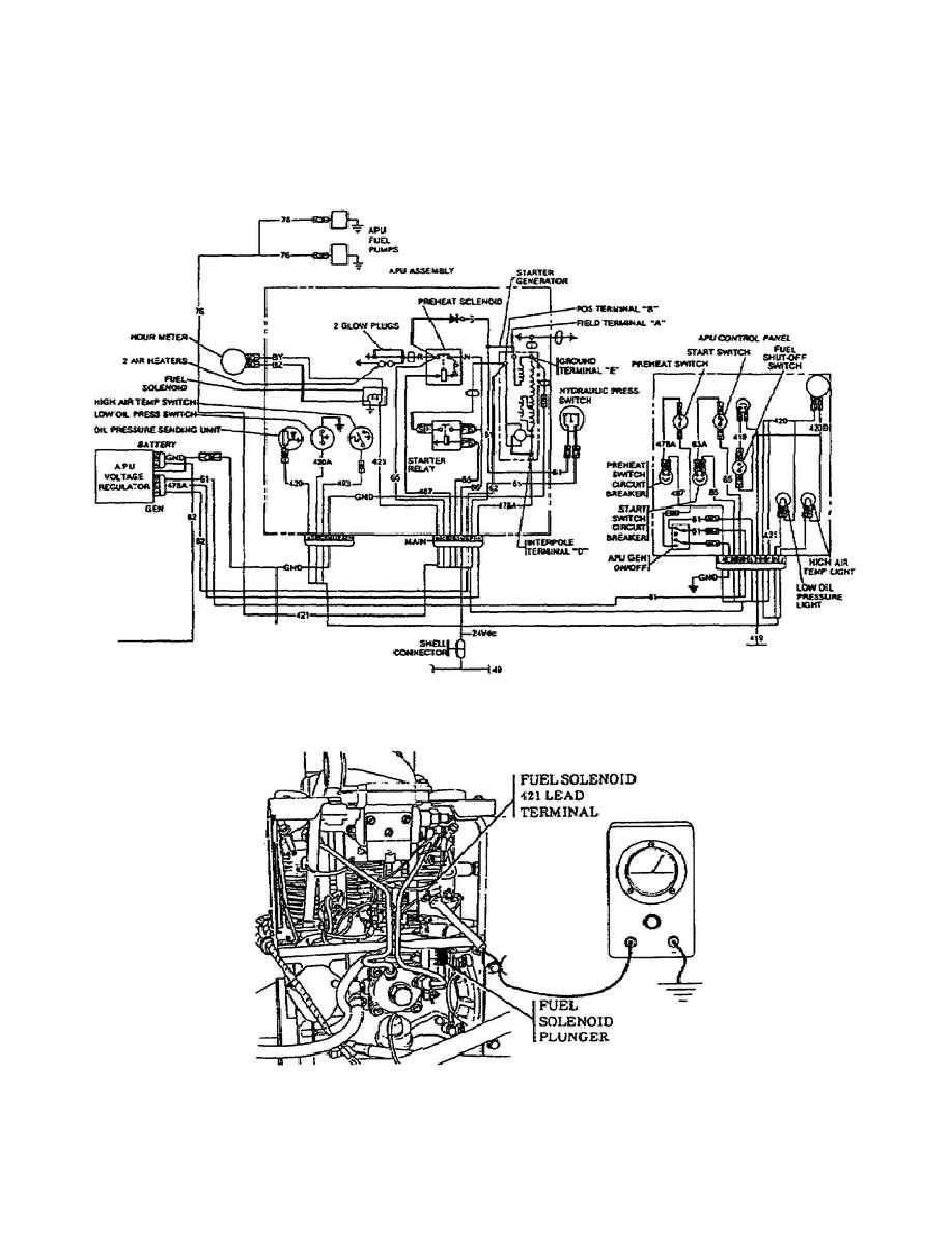
When the fuel solenoid plunger fails to function properly, a voltage check
at fuel solenoid 421 lead terminal must be made.  Place the red multimeter
probe on 421 terminal and ground the black probe.  Set the MASTER switch and
the FUEL SHUT OFF switch to the ON position.  If voltage is indicated during
this test, the fuel solenoid is defective and  you must notify Support
Maintenance.  Refer to Figure 13 when performing this test.
Figure 12.
APU Electrical Diagram.
Figure 13.
Fuel Solenoid Plunger and Lead Terminal 421.
15
OD1702


Western Governors University

< Previous Page
Index ^
Next Page >

Privacy Statement
Press Release
Contact

© Copyright Integrated Publishing, Inc.. All Rights Reserved. Design by Strategico.