

METAL BODY REPAIR - OD1653 - LESSON 1/TASK 1
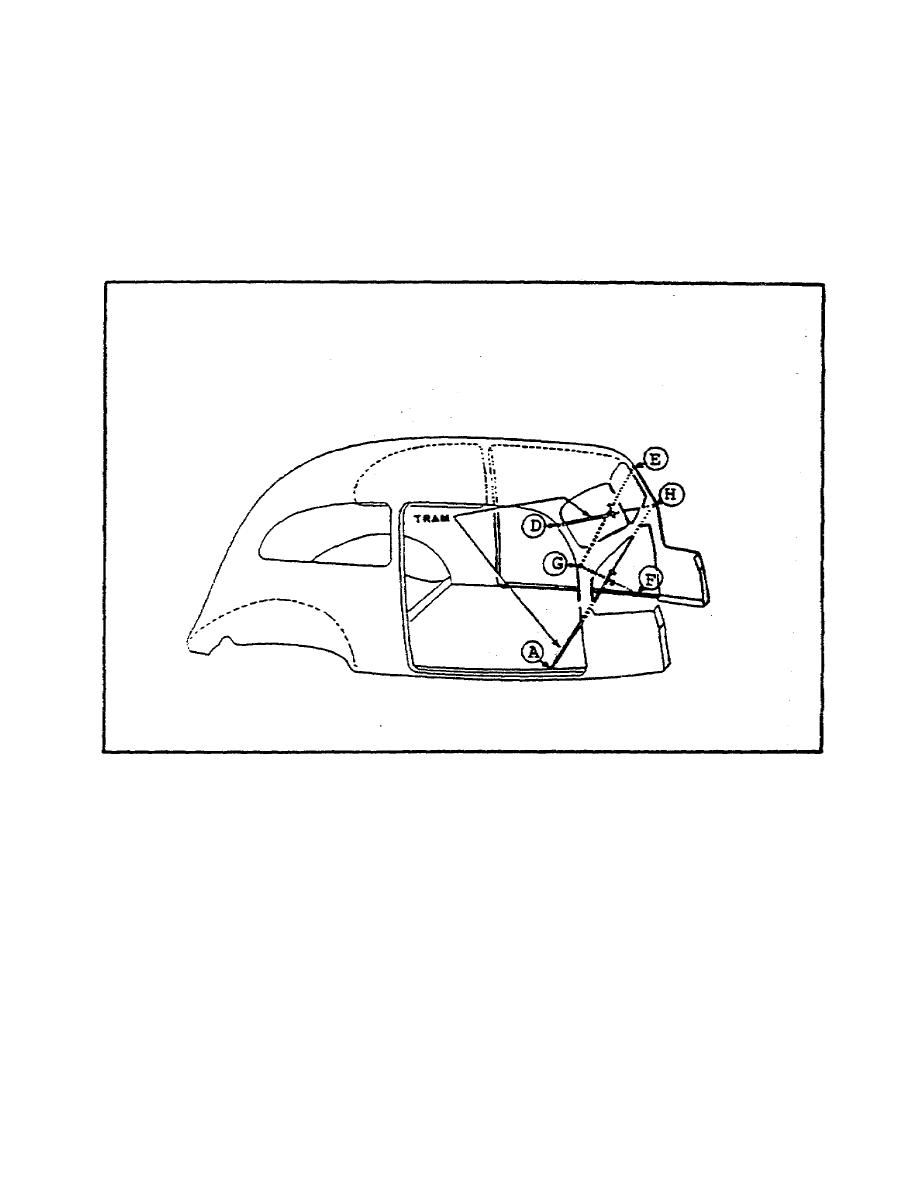
(19) Because the front section is logically divided into two rectangles,
one above the instrument panel and one below, each of these should next be
tested separately to determine whether the instrument panel is in line
(figure 21). This time, points G and E are located at corresponding top
hinge bolt heads on the opposite cowl hinge pillars. The test is now made
just as before with the tram, which this time should show diagonals E G and
D H to be equal, and G F and A H to be equal.
FIGURE 21. CHECKING INSTRUMENT PANEL ALIGNMENT.
(20) The center section is tested twice. First points I and J (figure 22
on the following page) are located on the opposite door corresponding to
points C and B of the door opening test. The diagonals B I and C J must be
equal. Then points K and L are located at corresponding locations in the
middle of the center pillar, such as the pressed molding in the body panel.
If the tram shows B L and J K to be equal, center alignment is satisfactory.
32


 Previous Page
