

ELECTRONIC PRINCIPLES - OD1647 - LESSON 1/TASK 1
i. RC Time Constant. The time required to charge a capacitor
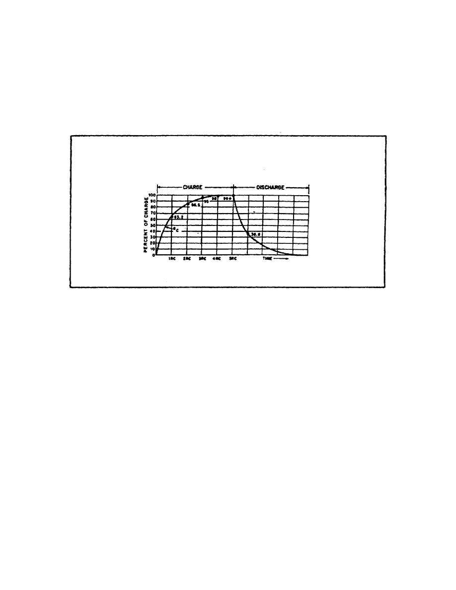
to 63% (actually 63.2%) of maximum voltage, or to discharge it
to 37% (actually 36.8%) of its final voltage is known as the
TIME CONSTANT (TC) of the circuit. The charge and discharge
curves of a capacitor are shown in figure 36. Note that the
charge curve is like the curve in figure 34, graph 1), on page
53, and the discharge curve like the curve in figure 34, graph B.
FIGURE 36. RC TIME CONSTANT.
The value of the time constant in seconds is equal to the
product of the circuit resistance in Ohms and the circuit.
capacitance in farads. The value of one time constant is
expressed mathematically as t=RC. Some forms of this formula
used in calculating RC time constants are:
t(in seconds)
= R (in Ohms) x C(in farads)
t(in seconds)
= R (in megohms) x C(in microfarads)
t(in microseconds)
= R (in Ohms) x C(in microfarads)
t(in microseconds)
= R (in megohms) x C(in picofarads)
j. Universal Time Constant Chart. Because the impressed
voltage and the values of R and C or R and L, in a circuit are
usually known, a UNIVERSAL, TIME CONSTANT CHART (figure 37 on
the following page)can be used to find the time constant of the
57


 Previous Page
