

ELECTRONIC PRINCIPLES - OD1647 - LESSON 1/TASK 1
resistor decreases until at t1 it has reached a value of zero.
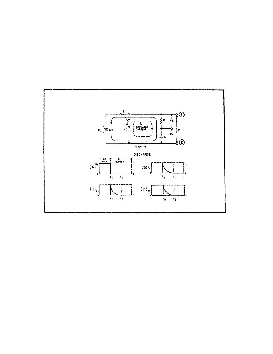
Graph D, figure 35, shows the voltage across the capacitor (ec)
and as time progresses toward time t1, the energy stored in the
capacitor is depleted. At the same time, the voltage across the
resistor is decreasing, the voltage (ec) across the capacitor is
decreasing, until, at time t1, the voltage (ec) reaches zero.
FIGURE 35. DISCHARGE OF AN RC SERIES CIRCUIT.
Comparison of graph A with graph D of figure 35 indicates the
effect that capacitance has on a change in voltage. If the
circuit had not contained a capacitor, the voltage would have
cease at the instant S1 was opened at time to. Because the
capacitor is in the circuit, voltage is applied to the circuit
until the capacitor has discharge completely at t1. The effect
of capacitance has ten been to oppose this change in voltage.
56


 Previous Page
