PRIN. OF DRAFTING AND SHOP DRAWINGS - OD1641 - LESSON 1/TASK 4
(8) Coordinate System.
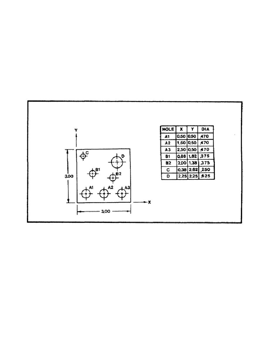
The coordinate system is a dimensioning system based on
the mathematical x-y coordinate system.
It is usually only used to dimension an
object that contains a great many holes, for example, an electrical chassis. It is
particularly well-suited to computer use and to numerically controlled tape
machines.
Each hole on the given surface is located relative to an x-y coordinate system,
then all values are listed in a chart. The overall dimensions are not included in
the chart but are located on the picture part of the drawing.
Figure 75 is an
example of an object dimensioned by using the coordinate system.
FIGURE 75.
COORDINATE SYSTEM.
(9) Tabular Dimensions.
Often manufacturers will produce a part in several
different sizes. Each part will have the same basic shape, but the part will vary
in overall size.
To save having to dimension each part individually, a system
called tabular dimensioning is used. Figure 76 (on the following page) illustrates
an example of tabular dimensioning.
To read tabular dimensions, look up the part number in the table and substitute the
given numerical values for the appropriate letters in the figure.
For example,
part number 1003 (according to the
84


 Previous Page
