

PRIN. OF INTERNAL COMBUSTION ENGINES - OD1619 LESSON 1/TASK 2
There are no special pockets, cells, or passages to aid the mixing of the fuel and
air. This type of chamber requires a higher injection pressure and a greater
degree of fuel atomization than is required by other combustion chambers to obtain
an acceptable level of fuel mixing. This chamber design is very susceptible to
ignition lag.
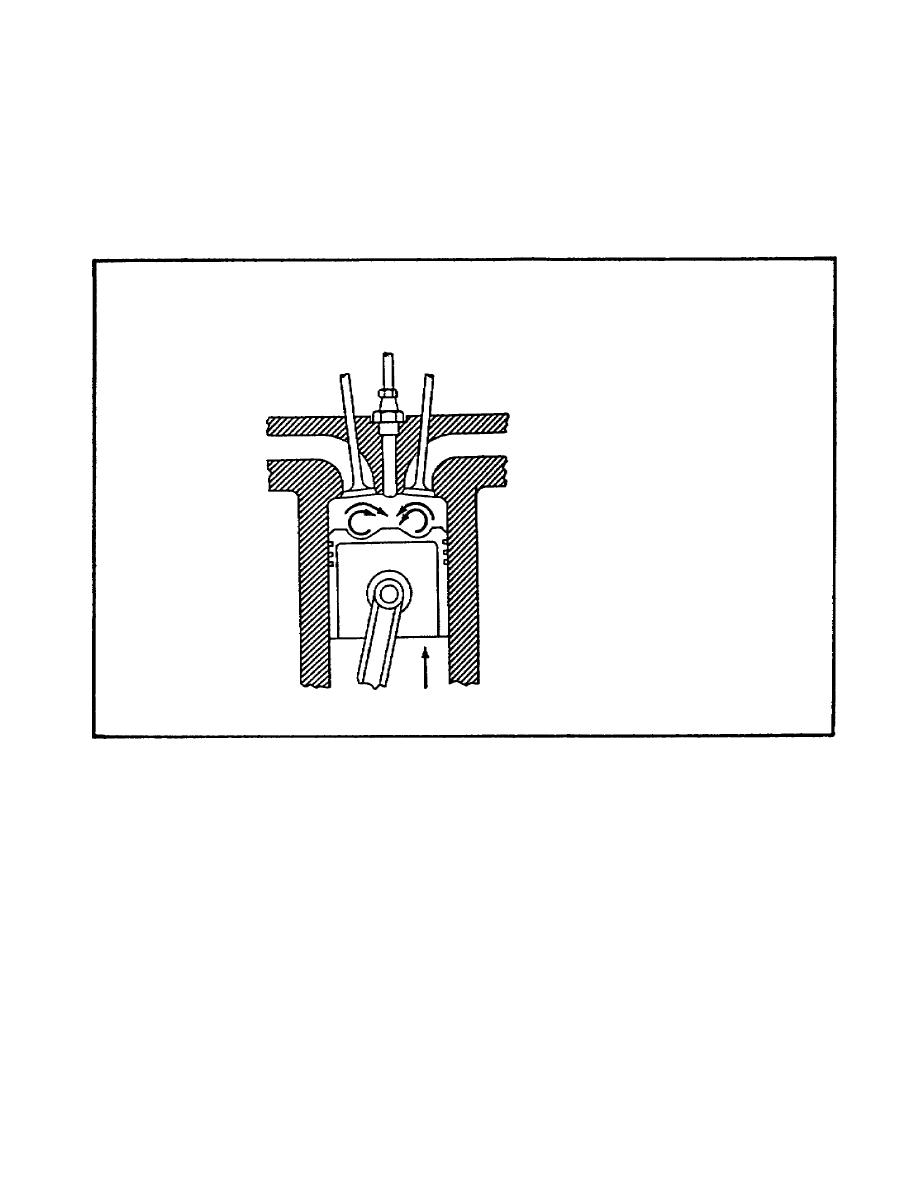
FIGURE 34. OPEN COMBUSTION CHAMBER.
c. Precombustion Chamber (figure 35 on the following page). The precombustion
chamber is an auxiliary chamber at the top of the cylinder. It is connected to the
main combustion chamber by a restricted throat or passage. The precombustion
chamber conditions the fuel for final combustion in the cylinder. A hollowedout
portion of the piston top causes turbulence in the main combustion chamber as the
fuel enters from the precombustion chamber to aid in mixing with air. The
following steps occur during the combustion process:
(1) During the compression stroke of the engine, air is forced into the
precompression chamber and, because the air is compressed, it is hot. At the
beginning of injection, the precombustion chamber contains a definite volume of air.
39


 Previous Page
