

4. A very basic circuit consists of a power source, a unit to be operated,
and a wire to connect the two together.
a. Series Circuits.
(1) Laws of series circuits.
(a) A series circuit has only one path for current to flow.
(b) Amperage remains the same in all parts of a series circuit.
(c) When resistance is added in series, the total resistance
increases and current decreases.
(d) The sum of all different voltage drops is equal to the applied
voltage.
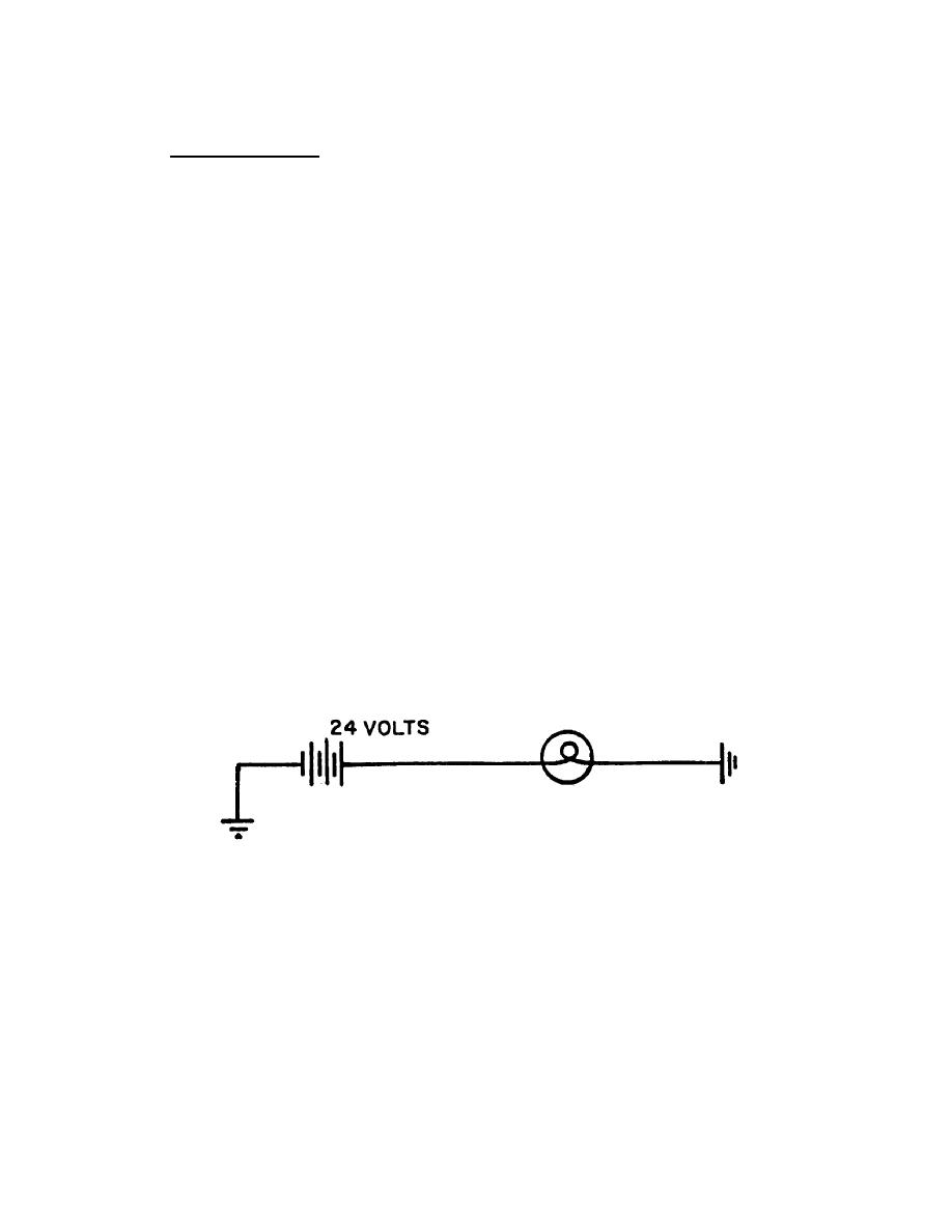
(2) Figure 16 shows a series circuit consisting of one or more units
connected in series (negative to positive) to form a single path for current to
flow. Most every one is familiar with the old type of Christmas tree lights
where all of the bulbs go out when any one of the bulbs burn out. These lights
are connected in series (negative to positive). A break anywhere in the
circuit will cause all of the lights to go out.
Figure 16. Series Circuits.
10
OD0611


 Previous Page
