

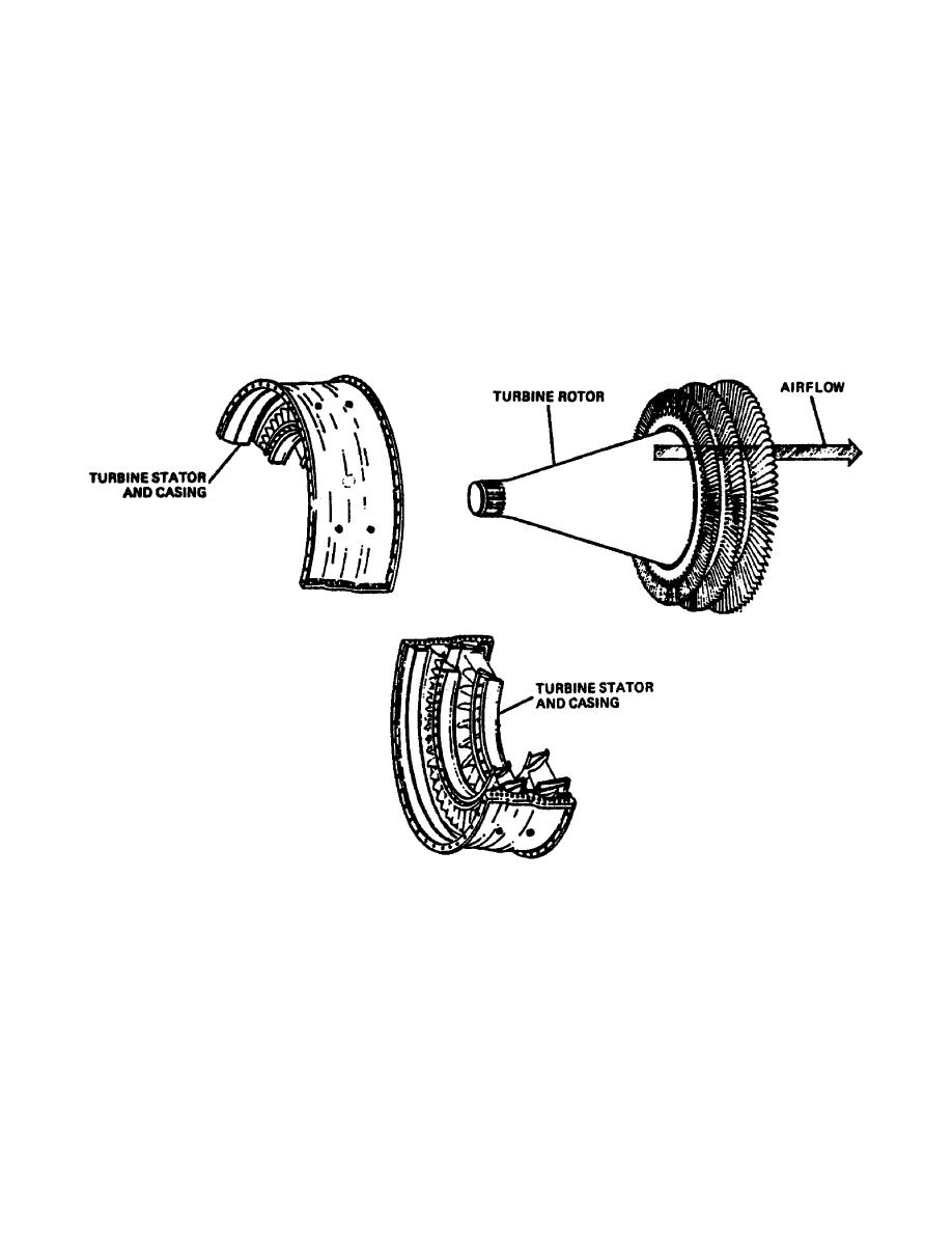
(b) Axial Flow. The axial flow turbine (Figure 126) is composed
of two main elements: a set of stationary vanes and a turbine rotor or rotors.
The axial flow turbine rotors are categorized into two basic types: impulse and
reaction. The modern turbine consists of a combination of these two called the
impulsereaction turbine. Each is discussed below. As the name implies, the
axial flow turbine wheel extracts kinetic energy from the moving gases that
flow in a relatively straight line, parallel to the axis of rotation. The
turbine wheel is used as the rotating element. Stationary vanes are used to
deliver the gas to the next stage in the most efficient way possible.
Figure 126. Axial Flow Design.
37
OD0610


 Previous Page
